
Manual

ASSEMBLY
TOOLS REQUIRED FOR ASSEMBLY
(2) 3/4" Wrenches
(2) 9/1 6" Wrenches
(2) 1-1/8" Wrenches or Adjustable Wrenches
(1) 1-5/16" Wrench or 12" Adjustable Wrench
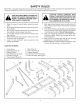
_ CAUTION: THE CULTIVATOR TANGS
HAVE SHARP POINTS. USE CARE
WHEN HANDLING AND ASSEMBLING
THE TANGS. WEAR GLOVES FOR
EXTRA PROTECTION AGAINST CUTS.
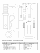
Remove all loose parts and the hardware package
from the shipping carton. Lay out and identify each
part and the hardware as shown on pages 2 and 3. Be
sure the carton is empty before it is discarded.
1 ,
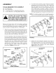
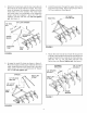
Attach nine cultivator tangs and tang support straps
to the cultivator frame assembly using one 3/8" U-
bolt and two 3/8" Nylock hex nuts for each tang. Be
sure to install a tang support strap between each
tang and the frame assembly. See figure 1.
For even spacing, install five tangs on the rear of
the frame and four tangs on the front of the frame.
For the rear tangs, put a tang at each end of the
frame assembly and a tang in the center. Then put
the other two rear tangs midway between the
middle and end tangs as shown in figure 1. When
attaching the front tangs, center them between
the rear tangs as shown. Once the tangs are
positioned, tighten all hex nuts.
CULTIVATOR
TANG
318" NYLOCK
HEX NUT
6
TANG
SUPPORT
STRAP I
FRONT
(FOUR TANGS)
CULTIVATOR
FRAME ASSEMBLY
BACK
(FIVE TANGS)
FIGURE 1
2,
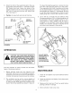
Turn the frame assembly upright. Attach two depth
gauge bars to the frame using a 3/8" U-bolt and
two 3/8" Nylock hex nuts for each bar. Put each
depth gauge bar next to each outside tang on the
rear of the frame as shown in figure 2. Use the
holes in each bar that will give the desired working
depth, if known at this time. Use matching holes in
both depth gauge bars to keep the cultivator level.
NOTE: For effective depth control a depth gauge bar
must not be located directly behind a front tang.
DEPTH
_GAUGE
BAR
WORKING
DEPTH
3/8"
U-BOLT I
\ i
3/8" NYLOCK
_ _] HEX NUT
GAUGE BAR
FIGURE 2
,
Attach two mast extension straps to the front of
the frame using two 1/2" x 2-3/4" hex bolts and two
1/2" Nylock hex nuts. Point the bent end of each
strap toward the outside of the frame. Do not
tighten yet. See figure 3.
MAST EXTENSION
STRAP (RIGHT
SIDE)
FIGURE 3