
Owner`s manual


ASSEMBLY
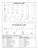
TOOLS REQUIRED FOR ASSEMBLY
(2)
(1)
(2)
(2)
(1)
(1)
7/1 6" Wrenches
1/2" Wrenches
9/1 6" Wrenches
3/4" Wrenches or 10" Adjustable Wrenches
Pliers
Grease Gun
Remove all loose parts and the hardware package
from the shipping carton. Lay out and identify each
part and the common hardware as shown on pages 2
and 3. Be sure the carton is empty before discarding.
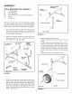
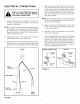
1 .
Insert the long wires from the switch through the
hole under the hitch bracket in the side of the
drawbar. Route the wires out through the rear end
of the drawbar. See figure 1.
2. Attach the drawbar assembly to the trailer frame
assembly using two 1/2" x 2-3/4" hex bolts and
1/2" Nylock hex nuts. See figure 1.
112" x 2-314" TRAILER
1/2" NYLOCK
HEX BOLT FRAME
HEX.UT
l 112" x 2-3/4"
HEX BOLT
112" NYLOCK
HEX NUT '_
HOLE IN
SIDE OF DRAWBAR
DRAWBAR ASSEMBLY
WIRE DETAIL
FIGURE 1
.
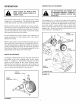
Slide an axle assembly up through one end of the
trailer frame, with the shaft of the axle pointing
out. Pin the axle to the frame using a height adjust
pin and a haircotter pin. Repeat this step for the
other axle assembly on the opposite end of the
trailer. Be sure both axles are pinned at the same
height. See figure 2.
HEIGHT
ADJUST PIN
TRAILER FRAME
ASSEMBLY
/
/
/
/ i
HAIRCOTTER PIN
/
AXLE SHAFT
AXLE
ASSEMBLY
J
FIGURE 2
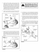
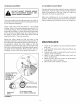
4.
Install the wheels (see figure 3):
• Install a cotter pin in the inner hole of the axle
shaft.
• Install a wheel on the axle shaft with a 1" flat
washer on each side of the wheel. Be sure the
air stem is toward the outside for easy access.
• Install another cotter pin in outer hole of axle.
• Install a hub cap, snapping it onto the washer.
• Fill the wheel hubs with grease using a grease
gun.
• Repeat this step for the opposite axle.
AXLE SHAFT
1" FLAT
WASHER
-_ COTTER PINS
/
HUB CAP
1" FLAT WASHER
WHEEL
FIGURE 3