™ owners manual MANUAL DEL USUARIO NOTICE D’UTILISATION Model No. Modelo No. Modèle No. 45-03291 CAUTION: Read Rules for Safe Operation and Instructions Carefully PRECAUCION: Lea cuidadosamente los Procedimientos e Instrucciones para la Operación Segura de la Máquina. ATTENTION: Lire et suivre attentivement les instructions et consignes de sécurité de cette notice. 175 LB.
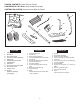
CARTON CONTENTS (Loose Parts in Carton) CONTENIDO DE LA CAJA (Partes Sueltas en la Caja) CONTENU DU CARTON (Pièces en Vrac Dans le Carton) 2 4 3 1 10 OF F ON 10 5 9 8 7 6 5 4 3 2 9 1 8 6 11 7 12 ENGLISH 1. 2. 3. 4. 5. 6. 7. 8. 9. 10. 11. 12. Hopper Assembly Braces (4) Flow Control Rod Flow Control Mounting Tube Wheels (2) Hitch Extension Bracket Hitch Bracket Hitch Tube Flow Control Mount Bracket Flow Control Arm Hopper Cover Screen Hardware Package (see page 3) ESPAÑOL 1. 2. 3. 4.
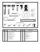
SHOWN FULL SIZE F A B C D E G H I K L J M N O NOT SHOWN FULL SIZE P KEY A B C D E F G H I J K QTY. 4 6 2 2 1 8 4 2 4 7 4 Q S R DESCRIPTION Hex Bolt, 5/16" x 1-3/4" Hex Bolt, 1/4" x 1-3/4" Hex Bolt, 3/8" x 3/4" Hex Bolt, 1/4" x 1" Carriage Bolt, 1/4" x 3/4" Nylock Hex Nut, 1/4" Nylock Hex Nut, 5/16" Nylock Hex Nut, 3/8" Nylon Washer Flat Washer, 5/16" Flat Washers 3/4" 3 KEY QTY.
ENGLISH RULES FOR SAFE OPERATION Any power equipment can cause injury if operated improperly or if the user does not understand how to operate the equipment. Exercise caution at all times when operating equipment. • • • • • Read the towing vehicle owners manual and towing vehicle safety rules. Know how to operate your tractor before using the broadcast spreader attachment. Read the chemical label instructions and cautions for handling and applying the chemicals purchased for spreading.
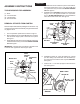
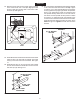
ENGLISH ASSEMBLY INSTRUCTIONS 4. Assemble the four hitch braces in pairs to the inside of the hopper frame using a 1/4" x 1-3/4" hex bolt (B) and 1/4" nylock hex nut (F) on each side. DO NOT TIGHTEN YET. See figure 2. 5. Assemble the two OUTER hitch braces to the hitch tube using a 1/4" x 1-3/4" (B) hex bolt and a 1/4" nylock hex nut (F). DO NOT TIGHTEN YET. Do not assemble the inner hitch braces at this time. See figure 2.
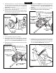
ENGLISH 14. Assemble the two INNER hitch braces to the flow control mounting tube using a 1/4" x 1-3/4" hex bolt (B) and a 1/4" nylock hex nut (F). DO NOT TIGHTEN YET. See figure 6. 15. TIGHTEN all nuts and bolts assembled up to this point. Do not collapse the tubes when tightening. 8. Assemble a spacer (P), a 3/4" flat washer (K), a wheel (air valve facing out) and another 3/4" flat washer (K) onto the end of the axle that has both the large and small holes. See figure 4. 9.
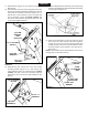
ENGLISH 17. Assemble the vinyl grip (T) onto the flow control arm. See figure 8. 18. Insert the flow control arm down through the slot in the flow control bracket. Assemble the small hole of the flow control link (U) to the flow control arm using a 1/4" x 1" hex bolt (D), a nylon washer (I) and a 1/4" nylock hex nut (F) as shown in figure 8. Tighten carefully. The flow control link should be snug but should pivot with no more than slight resistance. 20.
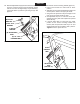
ENGLISH 22. Place the adjustable stop (R) into the "ON" end of the slot in the top of the flow control mounting bracket. Secure with the 1/4" x 3/4" carriage bolt (E), a nylon washer (I), a 5/16" flat washer (J) and the nylon wing nut (Q). See figure 12. (Q) NYLON WING NUT OF F (J) 5/16" FLAT WASHER (I) NYLON WASHER 23. Position the flow control mounting bracket (figure 13). a. Push on flow control arm until it locks in "OFF" position. b.
ENGLISH 27. For most vehicles, assemble the hitch extension bracket to the holes in the hitch tube shown at the top of figure 16. Use two 1/4" x 1-3/4" hex bolts (B) and 1/4" nylock hex nuts (F) tightened only finger tight. Attach the spreader hitch to your vehicle hitch. Check for interference with the spreader directly behind and out to both sides of the vehicle. Lift the spreader at each position to make sure there is no interference with the spreader's flow control.
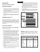
ENGLISH OPERATION 10. To insure uniform coverage, make each pass so that the broadcast pattern slightly overlaps the pattern from the previous pass as shown in figure 17. The approximate broadcast widths for different materials are shown in the application chart on this page. 11. When broadcasting weed control fertilizers, make sure the broadcast pattern does not hit evergreen trees, flowers or shrubs. 12. Heavy moisture conditions may require a cover over the hopper to keep contents dry.
ENGLISH MAINTENANCE SERVICE AND ADJUSTMENTS CHECK FOR LOOSE FASTENERS 1. Before each use make a thorough visual check of the spreader for any bolts and nuts which may have loosened. Retighten any loose bolts and nuts. REPLACING SLOTTED GEAR 1. If the axle, slotted gear and sprocket assembly is disassembled, mark down the positions of the parts as they are removed.The drive wheel and sprocket positions in relation to the slotted gear determine which direction the spreader plate will spin.
ESPAÑOL REGLAS PARA OPERACIONES SEGURAS Recuerde, cualquier equipo motorizado puede causar lesiones si se opera incorrectamente o si el usuario no entiende cómo operar el equipo. Sea precavido en todo momento al usar equipo motorizado. • • • • • • Lea el manual del propietario y las reglas de seguridad del vehículo de arrastre. Aprenda cómo operar su tractor antes de usar el implemento Esparcidor de Lanzado.
ESPAÑOL 4. 5. 6. 7. 8. 9. 10. 11. 12. 13. 14. 15. 16. 17. 18. 19. Instale los cuatro puntales de enganche en el interior del marco de la tolva – dos a cada lado - usando un perno hexagonal (B) y una tuerca de cierre hexagonal (F) a cada lado. NO APRIETE TODAVIA. Vea la Figura 2. Instale los dos puntales de enganche EXTERIORES en el tubo de enganche usando un perno hexagonal (B) y una tuerca de cierre hexagonal (F). NO APRIETE TODAVIA. No instale en este paso los puntales de enganche interiores.
ESPAÑOL OPERACIÓN 10. Para garantizar un cubrimiento uniforme, realice cada pasada superponiendo ligeramente el patrón de lanzado de la pasada anterior, según se muestra en la figura 17. Los anchos aproximados de lanzado para los diferentes materiales, se muestran en el cuadro de aplicación en esta página. 11. Cuando aplique fertilizantes para control de hierbas o malezas, asegúrese de que el patrón de lanzado no llegue a los árboles de verde perenne, a las flores ni a los arbustos. 12.
ESPAÑOL MANTENIMIENTO ALMACENAMIENTO REVISE SI HAY ELEMENTOS DE AJUSTE SUELTOS 1. Antes de cada uso, realice una revisión visual detallada del esparcidor en busca de pernos o tuercas sueltos o flojos. Vuelva a apretar los pernos o las tuercas flojas. 1. 2. Lave el interior de la tolva y el exterior del esparcidor y séquelos bien antes de guardar la unidad. Almacénela en un área limpia y seca. REVISE SI HAY PARTES GASTADAS O DAÑADAS 2. Antes de cada uso, revise si hay partes gastadas o dañadas.
FRANÇAIS CONSIGNES DE SÉCURITÉ Tout appareil mécanique risque de provoquer des blessures si ce dernier n’est pas utilisé correctement ou si l’utilisateur ne sait pas comment l’utiliser. Faites preuve de prudence à tout moment lorsque vous utilisez un appareil mécanique. • • • • • Lisez cette notice d’utilisation et les consignes de sécurité avant de tenter d’assembler ou d’utiliser la remorque. Veillez à bien connaître le fonctionnement du tracteur avant d’atteler la remorque à l’épandeur.
FRANÇAIS 4. 5. 6. 7. 8. 9. 10. 11. 12. 13. 14. 15. 16. 17. 18. 19. 20. Accrochez le bout plié de la bielle de contrôle du débit dans le trou de la fixation de la plaque coulissante située à proximité du fond de la trémie. Voir figure 10. 21. Placez une rondelle plate de 5/16 po. (J) sur l’autre extrémité de la bielle de contrôle du débit. Introduisez l’extrémité de la bielle dans la fente courbée du support de montage du contrôle du débit puis dans le trou de la biellette de contrôle du débit.
FRANÇAIS UTILISATION 10. Pour une couverture optimale et afin d’éviter de manquer des zones ou de laisser des traces de passages, chevauchez les traces précédentes comme illustré à la figure 17. Les portées approximatives des différentes matières sont indiquées dans le tableau des débits de cette page. 11. Faites attention lorsque vous utilisez l’épandeur avec des herbicides et désherbants et veillez à ce que ces produits ne touchent pas les buissons, les fleurs, etc. 12.
FRANÇAIS ENTRETIEN ET MAINTENANCE REMISAGE VÉRIFIER QUE LA VISSERIE N’EST PAS DESSERRÉE 1. Avant toute utilisation, vérifiez attentivement que les boulons et les écrous de l’épandeur ne sont pas desserrés. Serrez tout boulon ou écrou desserré. 1. 2. VÉRIFIER QUE LES PIÈCES NE SONT PAS USÉES OU ENDOMMAGÉES 2. Vérifiez que les pièces ne sont pas usées ou endommagées avant chaque utilisation. Réparez ou remplacez la pièce si nécessaire.
REPAIR PARTS FOR BROADCAST SPREADER MODEL 45-03291 47 44 42 34 45 65 54 54 58 40 1 54 9 30 40 4 5 6 7 8 9 10 54 35 39 39 11 51 54 39 41 11 35 2 60 63 B A 31 40 9 5 29 58 3 59 26 27 4 12 9 28 D 46 49 15 35 9 C 32 7 52 E 36 29 23 24 50 50 A 55 13 7 13 23 21 18 62 33 19 E 9 40 57 6 7 37 9 25 10 43 20 19 21 22 17 37 35 49 9 14 D 15 16 48 C 50 50 3 37 4 24 2 9 9 53 1 13 39 58 F ON 38 61 8 39 OF 64 B 9 37 20 56
REPAIR PARTS FOR BROADCAST SPREADER MODEL 45-03291 REF. NO. 1 2 3 4 5 6 7 8 9 10 11 12 13 14 15 16 17 18 19 20 21 22 23 24 25 26 27 28 29 30 31 32 33 34 PART NO. 44480 43882 65129 44462 23753 23758 HA21362 24857 47189 43808 43084 44180 47810 48864 48511 25080 23014 24914 43851 43871 1540-32 1540-162 47615 47683 25305 04367 43850 44468 44285 25672 48934 43070 43054 48586 QTY.
NOTES 22
NOTES 23
the fastest way to purchase parts www.speedepart.com © 2002 Agri-Fab Inc. REPAIR PARTS Agri-Fab, Inc. 809 South Hamilton Sullivan, IL. 61951 217-728-8388 www.agri-fab.