
Manual

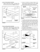
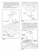


14.Placethe motorassemblydowninto the hopper,
insertingthespreadershaftthroughtheplasticbush-
ing in the bottomof the hopper.Fastenthe motor
mountbrackettothehopperusingfour5/16"x 1"hex
bolts,5/16"flat washers,nylonwashersand5/16"
nylocknuts.Seefigure8.
15.Slidethesealdownthespreadershaftagainstthe
topof thehopperbushing.Seefigure8.
5/16" NYLOCK NUT
SEAL
\
5/16" x 1"
HEX BOLT
WASHER
5/16"FLAT WASHER
FIGURE 8
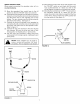
17. Slide the impeller up onto the spreader shaft and
secure it with a 1/8" x 1-1/4" cotter pin. See figure 9.
IMPELLER
1/8" x 1-1/4"
COTTER PIN
FIGURE 9
18. Attach the flow control to the motor mount bracket on
the spreader using the 5/16" x 1" carriage bolt, a
mounting clamp and a plastic knob. See figure 10.
NOTE: You can also attach to the rear rack if you use a
5/16" x 1-3/4" carriage bolt. If you attach to the rear
rack, you can loosely pre-assemble the clamp, bolt
and knob to the flow control. The clamp can then be
angled down through the slot in the rack.
PLASTIC KNOB
MOUNTING
CLAMP
5116" x 1"
I
CARRIAGE _......_ _
BOLT
I
L__ _ i¸ ! I
ii
5/16" x 1-3/4"
CARRIAGE
BOLT
FIGURE 10