
Manual

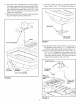


If you are using extension brackets:
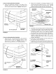
6. Attach the extension brackets to the legs of the
spreader frame. Use two 5/16" x 2" hex bolts and
5/16" nylock nuts per bracket. Tighten. See figure 4.
5/16" NYLOCK NUT
EXTENSION
BRACKET
FIGURE 4
If you are using extension brackets:
7. Attach the R.H. mounting bracket to the extension
bracket shown in figure 5 using two 5/16" xl" hex
bolts and 5/16" nylock nuts. Tighten. Repeat on the
other frame leg with the L.H. mounting bracket.
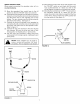
.
Attach the spreader's mounting brackets to the
vehicle's rear rack using four 5/16" x 1-3/4" carriage
bolts, mounting clamps and plastic knobs. Use the
adhesive pads to protect the rack. See figure 6.
MOUNTING
BRACKET
-....
5116" x 1-3/4"
CARRIAGE BOLT
ADHESIVE PAD
FIGURE 6
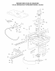
9. Assemble a seal (turned as shown at the top of figure
7) onto the motor shaft. Slide it up against the motor.
10. Assemble the impeller coupler onto the motor shaft
and secure it with a 1/8" x 1-1/4" cotter pin. Spread
the ends of the pin around the coupler. See figure 7.
11. Assemble the long end of the spreader shaft into the
impeller coupler and secure it with a 1/8" x 1-1/4"
cotter pin. Spread the ends of the pin around the
coupler. See figure 7.
12. Insert the 1/8" hairpin agitator into the middle hole in
the spreader shaft. See figure 7.
13. Assemble the second seal (turned as shown at the
bottom of figure 7) onto the end of the spreader shaft.
FIGURE 5
118" HAIRPIN
AGITATOR "------..._ <_
SEAL
IMPELLER
COUPLER
SPREADER
SHAFT
SEAL
FIGURE 7
5