
Instructions / Assembly


7
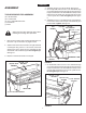
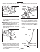
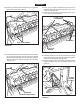
FIGURE 11
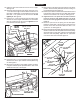
30.Pushaangebearingintoeachofthesevendrivedisks,
fromthesideshowningure12.
FIGURE 12
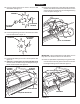
31.Pressangedbearingsintobothoftheendplates.See
gure13.
32. Place the 1/4" thick spacer onto the spike disk shaft
andtheninserttheshaftthroughtheangedbearingin
thelefthandendplate.Seegure13.
SPIKE DISK
(BB) LONG SPACER TUBE
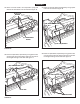
33.Placeashortspacertube,adrivedisk,a5/8"atwasher,
anotherdrivediskandasecond5/8"atwasherontothe
shaft.Fittheshortspacertubeontotheangedbearing
intheendplate.Seegure14.
FIGURE 13
FIGURE 14
FIGURE 15
IMPORTANT: When assembling the spike disks, be sure
they face in the direction shown in the instructions.
34. Place two spike disks, separated by a long spacer tube,
onto the shaft. Fit the long spacer tube onto the ends of
theangedbearingsinthedisks.Seegure15.
DRIVE DISKS
(S) 5/8" FLAT WASHER
(AA) SHORT SPACER
TUBE
(X) FLANGED
BEARING
SPIKE DISK
FLANGED
BEARING
FLANGED
BEARING
1/4" THICK SPACER
SPIKE DISK SHAFT
(X) FLANGED
BEARING
(X) FLANGED
BEARING
DRIVE DISK
ASSEMBLY
29.Pushtwoange bearingsinto each of the drivedisk
assemblies.Seegure11.
ENGLISH