
Instructions / Assembly


5
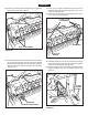
FIGURE 7
FIGURE 4
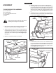
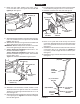
8. Fasten the hitch tubes together using three 5/16" x
2-1/4" hex bolts and 5/16" nylock hex nuts. Do not
tighten yet.Seegure4.
FIGURE 5
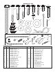
(L) 5/16" NYLOCK
HEX NUT (3)
(B) 5/16" x 2-1/4"
HEX BOLT (3)
(L) 5/16" NYLOCK
HEX NUT (2)
(V) HAIR COTTER
PIN (1/8")
(HH) HITCH PIN
(C) 5/16" x 2"
HEX BOLT (2)
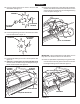
12.Assemblea1/2"atwasher,awheel,another1/2"at
washer and then a 1/2" jam nut onto a 1/2" x 4" hex bolt.
Tightenthenutngertightandthenbackoff1/4to1/2
turn.Seegure6.
13. Assemble the bolt and wheel to the transport tube using
a 1/2" nylock jam nut. Tighten the nut but don't collapse
thetube.Seegure6.
FIGURE 6
TRANSPORT
TUBE
(N) 1/2" NYLOCK
JAM NUT
(R) 1/2" FLAT
WASHER
(A) 1/2" x 4"
HEX BOLT
(M) 1/2" HEX
JAM NUT
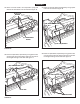
16.Screwa1/4"nylockhexnutallthewayontotheow
control link. Assemble the ferrule onto the link and then
start a 1/4" nylock hex nut one or two turns onto the link.
Seegure7.
17.Assembletheferruleintotheholeattheendoftheow
control lever using a 1/4" nylock hex nut. Tighten the
nut, leaving it loose enough that the ferrule can pivot.
Seegure7.
18.Assemblethegripontotheendoftheowcontrollever.
Seegure7.
FLOW
CONTROL
LEVER
(K) 1/4" NYLOCK
HEX NUT
(K) 1/4" NYLOCK
HEX NUT
(K) 1/4" NYLOCK
HEX NUT
(DD) FERRULE
(CC) FLOW
CONTROL
LINK
(EE) GRIP
ENGLISH
14. If the wheel does not spin freely, back off the nylock jam
nut and then the plain jam nut 1/4 to 1/2 turn each.
15.Assembleawheeltotheotherside.Seegure6.
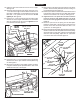
9. Assemble the hitch brackets to the hitch tubes using two
5/16" x 2" hex bolts and 5/16" nylock hex nuts. Do not
tighten.Seegure5.
10. Assemble the hitch pin through the hitch brackets and
securewiththehaircotterpin.Seegure5.
IMPORTANT: Do not collapse the at ends of the hitch
tubes when tightening the bolts in the next step.
11. Tighten, but do not overtighten the two 5/16" x 1-1/2"
hexboltsassembledingure1.
Tighten, but do not overtighten the two 5/16" x 1-3/4"
hexboltsassembledingures2and3.Thelifthandle
must be able to pivot.
Tightenthehexboltsassembledingure4and5.