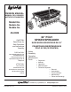
™ owners manual ManUAL DEL USUARIO NOTICE D'UTILISATION Model No. Modelo No. Modèle No. 45-0309 32" POLY SPIKER/SPREADER CAUTION: Read Rules for Safe Operation and Instructions Carefully PRECAUCION: Lea cuidadosamente los Porcedimientos e Instrucciones para la Operación Segura de la Máquina. ATTENTION: Lire et suivre attentivement les instructions et consignes de sécurité de cette notice.
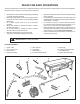
RULES FOR SAFE OPERATIONS Any power equipment can cause injury if operated improperly or if the user does not understand how to operate the equipment. Exercise caution at all times, when using power equipment. • • • • • • • Read this owner's manual before attempting to assemble or operate the spiker/spreader. Read the towing vehicle owner's manual and know how to operate the tractor before using the spiker/spreader attachment. Do not allow anyone to ride on or sit on the spiker/ spreader.
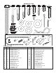
SHOWN FULL SIZE A C B D E G F J H T U S O I Q K L P R M V N NOT SHOWN FULL SIZE GG DD W X CC AA HARDWARE CHART REF. QTY. A B C D E F G H I J K L M N O P Q R 2 3 2 2 2 1 1 1 1 2 6 10 2 2 2 2 4 4 DESCRIPTION EE Z Y HH FF II BB REF. QTY.
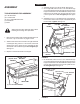
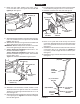
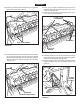
ENGLISH ASSEMBLY 4. Assemble the grip onto the lift handle. See figure 2. 5. On the right side, insert a 5/16" x 1-3/4" hex bolt through a 5/16" flat washer and then through the rear hole in the hopper and the hitch tube. Assemble the transport tube and then the lift handle onto the bolt and secure with a 5/16" nylock hex nut. Do not tighten yet. See figure 2. 6. Assemble a 5/16" x 1" hex bolt and 5/16" nylock hex nut to the bottom hole in the transport tube assembly and the lift handle. Tighten.
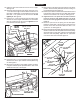
ENGLISH 8. Fasten the hitch tubes together using three 5/16" x 2-1/4" hex bolts and 5/16" nylock hex nuts. Do not tighten yet. See figure 4. 14. If the wheel does not spin freely, back off the nylock jam nut and then the plain jam nut 1/4 to 1/2 turn each. 15. Assemble a wheel to the other side. See figure 6.
ENGLISH 24. Move the flow control lever as far as it will go to the "OFF" position. Push the feed plate back as far as it will go to the closed position. See figure 10. 25. Place a nylon washer onto the bent end of the flow control link and then insert the link into the feed plate bracket. Secure it with a 3/32" x 3/4" cotter pin. See figure 10. 26.
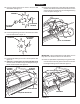
ENGLISH 33. Place a short spacer tube, a drive disk, a 5/8" flat washer, another drive disk and a second 5/8" flat washer onto the shaft. Fit the short spacer tube onto the flanged bearing in the end plate. See figure 14. 29. Push two flange bearings into each of the drive disk assemblies. See figure 11. DRIVE DISK ASSEMBLY DRIVE DISKS (X) FLANGED BEARING (X) FLANGED BEARING FIGURE 11 30. Push a flange bearing into each of the seven drive disks, from the side shown in figure 12.
ENGLISH 37. Place two 5/8" flat washers separated by a long spacer tube onto the shaft. See figure 18. 35. Place a 5/8" flat washer, the compression spring and another 5/8" flat washer onto the shaft. See figure 16. (S) 5/8" FLAT WASHER (BB) LONG SPACER TUBE (Y) COMPRESSION SPRING (S) 5/8" FLAT WASHER FIGURE 16 FIGURE 18 38. Place two spike disks, separated by a long spacer tube, onto the shaft. Fit the long spacer tube onto the ends of the flanged bearings in the disks. See figure 19. 36.
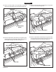
ENGLISH 39. Place two 5/8" flat washers separated by a long spacer tube onto the shaft. See figure 20. 41. Place one or two 5/8" flat washers onto the end of the spike disk shaft and secure the shaft with a 1/8" x 1-1/2" cotter pin. See figure 22. 42. Fasten the two drive disks to the shaft using two 1/8" x 1-1/2" cotter pins. See figure 22. (T) 1/8" x 1-1/2" COTTER PIN (BB) LONG SPACER TUBE DRIVE DISKS (S) 5/8" FLAT WASHER FIGURE 20 (S) 5/8" FLAT WASHER FIGURE 22 40.
ENGLISH OPERATION SETTING CHART HOW TO USE YOUR SPIKER/SPREADER 1. Refer to the instruction label on the material package and to the instruction decal on your spreader to help determine the proper spreader setting and application rate. Also see the Setting Chart on this page for a general range of settings for commonly used materials. 2. Determine the approximate square footage of the area to be covered and estimate the amount of fertilizer or seed required. 3.
ESPAÑOL REGLAS PARA UNA OPERACIÓN SEGURA Cualquier equipo motriz puede causar lesiones si no se opera correctamente o si el usuario no entiende la forma de operar el equipo. Tenga siempre cuidado cuando use un equipo motriz. • • • • • • • Lea este manual de instrucciones con mucho cuidado antes de tratar de armar u operar este surcador-esparcidor. Lea el manual de instrucciones del tractor y conozca bien la forma de operar el tractor antes de usar este equipo surcadoresparcidor.
ESPAÑOL INSTRUCCIONES DE ENSAMBLAJE H E R R A M I E N TA S ENSAMBLAJE (2) (2) (2) (1) (1) R E QU E R I DA S PA R A 11 Pase el pasador del enganche (HH) a través de las barras del enganche y asegúrelos con el pasador de horquilla (V). Vea la Figura 5. EL 12. Instale una arandela plana (R), una rueda, otra arandela plana (R) y entonces una contratuerca (M) sobre un tornillo hexagonal (A). Apriete la contratuerca hasta el final con sus dedos y entonces hágala retroceder de 1/4 a 1/2 vuelta.
ESPAÑOL 26. Ajuste la tuerca hexagonal inferior de ¼ de pulgada de nylock hasta que toque el fondo del regatón, luego ajuste la tuerca hexagonal superior de ¼ de pulgada de nylock hasta que sujete firmemente la parte superior del regatón. Vea la figura 10. 40. Coloque un disco surcador y un tubo espaciador corto (AA) sobre el eje. Asegure el tubo espaciador plástico sobre los extremos de los cojinetes de brida en el disco surcador y en la placa del extremo.
ESPAÑOL OPERACIÓN CUADRO DE AJUSTE FORMA DE USAR ESPARCIDOR SU EQUIPO SURCADOR- 1. Lea la etiqueta de instrucciones en el paquete de materiales y la calcomanía de instrucciones en el esparcidor para determinar el ajuste apropiado del esparcidor y la velocidad de aplicación. También vea, en el Cuadro de Ajuste de esta página, una gama general de los ajustes posibles para los materiales usados con mayor frecuencia. 2.
FRANÇAIS RÈGLES DE SÉCURITÉ D’UTILISATION Tout équipement à moteur peut causer des blessures s’il est mal utilisé ou si l’utilisateur ne sait pas comment l’utiliser. Il faut faire attention en permanence pour utiliser l’équipement à moteur. • • • • • • • Lire ce manuel du propriétaire avant d’essayer d’assembler ou d’utiliser la cramponneuse/répandeuse.
FRANÇAIS ASSEMBLAGE 11. Assembler la broche d’attelage (HH) à travers les supports d’attelage et attacher avec la goupille en épingle à cheveux (V). Voir la figure 5. OUTILS NÉCESSAIRES POUR L’ASSEMBLAGE 12. Monter une rondelle plate (R), une roue, une autre rondelle plate (R) et enfon un contre-écrou (M) sur un boulon à 6 pans (A). Serrer l’écrou avec la main, puis le reculer de 1/4 à 1/2 tour. Voir la figure 6.
FRANÇAIS 26. Serrer l’écrou hexagonal nylock inférieur de 1/4 po jusqu’à ce qu’il touche le fond de la virole, puis serrer l’écrou hexagonal nylock supérieur de 1/4 po jusqu’à ce qu’il soit placé contre le dessus de la virole. Voir la figure 10. 40. Placer un disque de crampon et tube entretoise court (AA) sur l’arbre. Installer le tube entretoise court sur les extrémités des paliers à bride dans le disque de crampon et dans la plaque d’extrémité.
FRANÇAIS FONCTIONNEMENT TABLEAU DE RÉGLAGE COMMENT UTILISER RÉPANDEUSE LA MATÉRIAU TYPE CRAMPONNEUSE/ 1. Se reporter à l’étiquette d’instructions sur l’emballage du matériau et à l’autocollant d’instructions sur la répandeuse pour aider à déterminer le réglage et le taux d’application appropriés de la répandeuse. En outre, voir le Tableau de réglage sur cette page pour une plage de réglages générique correspondant aux matériaux les plus fréquemment utilisés. 2.
NOTES 19
B 42 23 2 20 59 A 7 35 58 1 62 C 10 45 38 44 57 26 A 46 12 59 25 50 5 13 33 41 43 43 44 55 58 58 61 11 63 37 43 9 19 59 54 12 47 59 56 29 53 54 52 16 4 8 6 28 43 42 34 43 60 31 8 3 B F 48 13 20 32 39 59 24 14 13 21 10 59 40 30 58 15 22 17 57 C 42 23 42 18 36 51 27 49 PARTS FOR 32" POLY SPIKER/SPREADER MODEL 45-0309
DESCRIPTION Hopper Endplate, Right Hand Endplate, Left Hand Rivet, Pop Brace, Center Assembly, Agitator Shaft Bearing, Hex Flange Blade, Agitator Screw, Hex Washer Hd, #8-32 Washer, 17/32" x 1-1/2" x 10 Ga. Spacer, .8" I.D.x1" O.D. x .50" Lg. Washer, 17/32" x 1" x 16 Ga. Pin, Cotter 1/8" x 1-1/2" Spacer, .5" I.D. x1" O.D. x .59" Lg. Spacer, .66" I,D.x1.25" O.D. x .
the fastest way to purchase parts www.speedepart.com REPAIR PARTS Agri-Fab, Inc. 303 West Raymond Sullivan, IL. 61951 217-728-8388 www.agri-fab.com This document (or manual) is protected under the U.S. Copyright Laws and the copyright laws of foreign countries, pursuant to the Universal Copyright Convention and the Berne convention.