
Owners manual


5
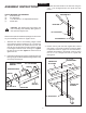
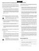
FIGURE 2
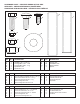
TOOLS REQUIRED FOR ASSEMBLY
(2) 9/16"Wrenches
(2) 3/4"Wrenches
(2) 1-1/8"Wrenchesor10"AdjustableWrenches
(1) GreaseGun
CAUTION: Discbladeshavesharpedges.Use
careinhandlingandassembly.Weargloves for
extra protection against cuts.
Removeloosepartsandhardwarepackagefromthecarton.
Layoutandidentifyasshownonpages2and3.
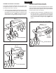
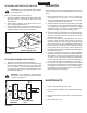
1. Assemblefour discs to each bearing hangerbracket
usingabearingsleeve(unplated),a3/4"x16"hexbolt,
eight3/4"atwashers,twospacersandtwo3/4"hex
nuts.Besurethediscsfacethesamedirectionrelative
tothehangerbracketasshowninthegure1.Tighten
thersthexnutandthentightenthesecondhexnut
againsttherst.
2. Lubricatethebearingsthroughthegreasettingsinthe
bearinghangerbracketassembliesuntilgreaseisforced
outthroughthebearings.
FIGURE 1
1/2" x 1-1/2"
CARRIAGE BOLT
1/2" NYLOCK NUT
DRAW BAR
HITCH BRACKET
3. Assemblethehitchbrackettothedrawbarusingtwo
1/2"x1-1/2"carriageboltsand1/2"nylocknuts.See
gure2.
4. Position the tray with the slots angled either toward
rearcenterorfrontcenterasshowningure3.(Refer
to Operation section on page 6 for more information.)
Assemblethedrawbartothebottomofthetrayusing
two1/2"x1-1/2"carriageboltsand1/2"nylocknuts.
Seegure3.
FIGURE 3
SPACER
BEARING SLEEVE
3/4" x 16"
HEX BOLT
DISC BLADE
3/4" HEX NUTS
3/4" FLAT WASHER
BEARING HANGER
BRACKET
SPACER
ASSEMBLY INSTRUCTIONS
ENGLISH
1/2" x 1-1/2"
CARRIAGE BOLT
1/2" NYLOCK NUT
THROWS SOIL
TO INSIDE
THROWS SOIL
TO OUTSIDE