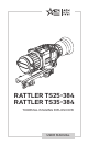
RATTLER TS25-384 RATTLER TS35-384 THERMAL IMAGING RIFLESCOPE USER MANUAL
© 2021 AGM Global Vision, LLC. All rights reserved. This documentation is subject to change without notice. No parts of this manual, in whole or in part, may be copied, photocopied, translated, or transmitted by any electronic medium or in machine-readable form without the prior written permission of AGM Global Vision, LLC. Approved for public release, distribution unlimited.
FCC INFORMATION Please take attention that changes or modification not expressly approved by the party responsible for compliance could void the user’s authority to operate the equipment. This equipment complies with FCC/IC RSS-102 radiation exposure limits set forth for an uncontrolled environment. FCC compliance: This product has been tested and found to comply with the limits for a Class B digital device, pursuant to Part 15 of the FCC Rules.
LIST OF CONTENTS TITLE PAGE Safety Summary 5 1. GENERAL INFORMATION 7 1.1 System Description 7 1.2 Key Features 8 2. OPERATING INSTRUCTIONS 9 2.1. Basic Operations 9 2.2 Main Function 15 2.3 Client Software Introduction 22 3. MAINTENANCE 23 3.1 Maintenance 23 3.2 Troubleshooting 24 4. WARRANTY INFORMATION 25 4.1 Warranty Information and Registration 25 5. SPECIFICATIONS 27 5.
SAFETY SUMMARY • • • • Read and follow all instructions Read all warnings Only use the attachments/accessories specified by the manufacturer All service must be provided by the manufacturer WARNING: This product contains natural rubber latex, which may cause potentially fatal allergic reactions! If you are allergic to latex, it is important that you strictly avoid exposure to products that contain it. WARNING: Always make sure your firearm is unloaded before you place the scope on the firearm.
WARNING: Sand and sea water can damage the optical coatings! WARNING: Do not point the device directly at the sun! WARNING: Image performance is dependent on scenery and atmosphere conditions. Contrast in the same image may vary as a function of the time of day due to the effect of the sun. For example, at sunset objects will have absorbed different levels of heat resulting in greater temperature differences and better contrast.
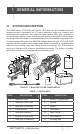
1 GENERAL INFORMATION 1.1 SYSTEM DESCRIPTION The AGM Rattler TS25-384 and Rattler TS35-384 are the compact thermal imaging scopes developed for 24 hours operation under any weather and environmental conditions. Two objective lens options allow the customer to choose perfect unit for your needs where 25 mm lens designed for short range shooting, while the 35 mm lens model will be great for medium range missions.
1.2 KEY FEATURES • • 384×288 thermal resolution, high sensitivity detector Image processing technology: Adaptive AGC, DDE, 3D DNR • 1024×768 resolution 0.
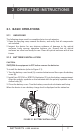
2 OPERATING INSTRUCTIONS 2.1. BASIC OPERATIONS 2.1.1 UNPACKING The following steps must be completed prior to each mission. 1. Open the carrying case, remove the device, and verify that all components are included. 2. Inspect the device for any obvious evidence of damage to the optical surfaces, body, eyecup, operation buttons, etc. Ensure that all optical surfaces are clean and ready for use. Clean all optical surfaces with a lens tissue. 2.1.
2.1.3 SELECT BATTERY TYPE You can change the battery type according to your need. Select the correct battery voltage in the device menu. 1. In the view mode, hold button to show the menu. 2. Select Battery Voltage menu item, and press button to switch the voltage. 2.1.4 CONNECTING THE DEVICE 1. Open the cable interface cover. 2. Connect the device and power adapter with a Type-C cable to power on the device. Alternatively, connect the device and PC to export files. FIGURE 2-2. CABLE INTERFACE 2.1.
TABLE 2-2. BUTTON FUNCTIONS BUTTON 2.1.6 FUNCTIONS POWER Press: Sleep Mode/Wake Up Device Hold: Power On/Off MODE Press: Switch Palettes CAPTURE Press: Capture Hold: Start/Stop Record Video MENU Press: Enable/Disable OSD Hold: Menu Operation ZOOM Press: Switch Digital Zoom Hold: Enable/Disable Reticle SHUTTER Press: Correct Non-uniformity of Display POWER ON AND OFF Power On Hold the POWER button for 4 seconds to power on the device. An image will appear on the display.
2.1.8 THERMAL VIEW OBSERVATION 1. Power on the riflescope. 2. Hold the riflescope and make sure the eyepiece covers your eye. 3. Adjust the diopter adjustment ring until the OSD text or image is clear. 4. Point the riflescope towards the target of the view. Bring the object into focus by rotate the objective focus ring. NOTE: You must perform the focus adjustment before any further use of the riflescope. 5.
2.1.13 SHUTTER RELEASE Press button in the view mode to release the shutter once for correction of the non-uniformity of display. 2.1.14 RECORD/CAPTURE Video Recording Hold button in the view mode and start recording. In the upper left corner, the recording time displays. Hold button again to stop recording. FIGURE 2-4. VIDEO RECORDING Snapshot Capturing Press button in the view mode, to capture picture. NOTE: • When capturing succeeds, the image freezes for 1 second and a prompt shows on the display.
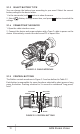
2.1.16 INSTALLING THE RATTLERN ON A PICATINNY/WEAVER RAIL WARNING: Always make sure your firearm is unloaded before you place the scope on the firearm. Reconfirm that the chamber is empty if you stop the procedure then resume later. Safe firearms handling rules should be followed at all times. The Rattler comes fully-assembled with a Picatinny/Weaver mount. The mount is attached to the scope with two screws. To install the Rattler on a Picatinny/ Weaver rail, perform the following (Figure 2-5) : 1.
Much like when the cam (E) is released, backward-moving springs will cause the nut (D) to slide back into its hole. NOTE: The eight-sided nuts of the mount lever-cam locks will only fit into their holes if turned in one of the discrete positions, using increments equal to 360°/8. 4. Verify that the adjusted lever-cam lock securely holds the weapon mounting rail. 5. Repeat the procedure to adjust the clamping device’s second lever-cam lock. 2.2 MAIN FUNCTIONS 2.2.
MENU ITEM SYMBOL NETWORK OPTION OFF Hotspot FUNCTION Enable or disable the Wi-Fi hotspot. PIP Upper Left/ Upper Middle/ Upper Right/ Close BORESIGHTING 5 Types of reticle Select the reticle type. Set the center of the reticle. COLOR White/ Green/ Red Select the reticle color. TRAJECTORY 5 Profiles FFC MEASURE Auto / Manual / External 0.8m/1.2m/ 1.8m/3.0m Target Height OFF One shot zero correction. Select the FFC mode. Enter distance measurement mode.
2. Select Battery Voltage menu item, and press battery voltage. button to switch the 2.2.3 BRIGHTNESS ADJUSTMENT 1. Hold button to show the menu. 2. Select Brightness menu item and press button to adjust the brightness. In White Hot mode, you can select one of five levels of the brightness to adjust the image lighter or darker. In Black Hot mode, the brightness of the image turns in the opposite way. 2.2.4 CONTRAST ADJUSTMENT 1. Hold button to go to the menu. 2.
2.2.7 PICTURE IN PICTURE MODE 1. Hold button to show the menu. 2. Select PIP menu item and enter PIP mode. The details show in the upper left corner. NOTE: When Boresighting is enabled, the PIP view is the detail of crosshair. When Boresighting is not enabled, the PIP view is the detail of central part. 3. Press button to switch the PIP type. Upper Left, Upper Middle, Upper Right, and OFF are selectable. NOTE: When you select Upper Right as PIP type, the OSD will be blocked. 4. Hold button to exit.
2.2.9 RETICLE COLOR You can change the color of the crosshairs. Enable reticle first. 1. Hold button to show the menu. 2. Select Color menu item and press button to switch the color of crosshair. White, Green, and Red colors are selectable. 3. Hold button to save and exit. 2.2.10 TRAJECTORY CORRECTING Enable the trajectory correction to shot the target with high accuracy by marking the offset between the big crosshair and small crosshair. Select the desired reticle type in the Boresighting menu. 1.
2.2.11 FLAT FIELD CORRECTION Flat Field Correction (FFC) function can correct non-uniformity of display. 1. Hold 2. Select button to show the menu. FFC menu item and press button to switch the FFC mode. Auto: The riflescope performs FFC automatically when switching on or rebooting the camera. Manual: Hold button in live view to correct the non-uniformity of display. External: Cover the lens cap, then hold non-uniformity of display. 3.
2.2.13 HOT TRACKING The device can detect the highest temperature spot in the scene and mark it on display. 1. Hold button to show the menu. / and press button to enable/disable hot spot mark 2. Select (marking the spot of highest temperature). When the hot spot mark is enabled, the mark displays in the spot of the highest temperature. When the scene changes, the mark moves. 2.2.
2.3 CLIENT SOFTWARE INTRODUCTION We recommend using T-Vision (V5.4.12 and below) software. Install the client software on your mobile phone first, and then connect your phone to the hotspot of the riflescope. Refer to chapter 2.2.6 for details of hotspot connection. NOTE: The device password is set by user at first activation. If the password was lost or forgotten, it can be reset. To make a reset, provide the following action: 1. When the riflescope is turned on, hold menu item and press 2.
3 MAINTENANCE 3.1 MAINTENANCE 3.1.1 CLEANING PROCEDURES 1. Gently brush off any dirt from the body of the device using a clean, soft cloth. 2. Moisten the cloth with fresh water and gently wipe down the external surfaces (except lenses). 3. Dry any wet surfaces (except lenses) using another dry, clean, soft cloth. 4. Using a lens brush, carefully remove all loose dirt from the lenses. 5. Dampen a cotton swab with ethanol and slowly, gently wipe down the lenses.
3.1.5 RESTORE DEVICE 1. Hold button to show the menu of device. Restore menu item and press 2. Select defaults according to the prompt. button to restore the device to 3.2 TROUBLESHOOTING Table 3-1 lists the most common malfunctions that may occur with your equipment. Perform the tests, inspections, and corrective actions in the order they appear in the table.
4 WARRANTY INFORMATION 4.1 WARRANTY INFORMATION AND REGISTRATION 4.1.1 WARRANTY INFORMATION This product is guaranteed to be free from manufacturing defects in material and workmanship under normal use for a period of three (3) years from the date of purchase.
obligation toward any third party of legal entity outside AGM Global Vision and the Customer; AGM Global Vision’s obligations under this Agreement extend solely to the Customer. AGM Global Vision’s liability hereunder for damages, regardless of the form or action, shall not exceed the fees or other charges paid to AGM Global Vision by the customer or customer’s dealer.
5 SPECIFICATIONS 5.
AGM Global Vision, LLC MAIN OFFICE 173 West Main Street PO Box 962 Springerville, AZ 85938 USA Tel. +1.928.333.4300 info@agmglobalvision.com www.agmglobalvision.com EUROPEAN OFFICE Andrey Lyapchev #7 Sofia, P.C. 1756 Bulgaria Tel. +35.988.412.5573 info@agmglobalvision.eu www.agmglobalvision.eu AGMglobalvision.