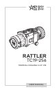
RATTLER TC19-256 THERMAL IMAGING CLIP-ON USER MANUAL
© 2021 AGM Global Vision, LLC. All rights reserved. This documentation is subject to change without notice. No parts of this manual, in whole or in part, may be copied, photocopied, translated, or transmitted by any electronic medium or in machine-readable form without the prior written permission of AGM Global Vision, LLC. If you have questions that are not covered in this manual, or need service, contact AGM Global Vision customer support for additional information prior to returning a product.
FCC INFORMATION Please take attention that changes or modification not expressly approved by the party responsible for compliance could void the user’s authority to operate the equipment. This equipment complies with FCC/IC RSS-102 radiation exposure limits set forth for an uncontrolled environment. FCC compliance: This product has been tested and found to comply with the limits for a Class B digital device, pursuant to Part 15 of the FCC Rules.
LIST OF CONTENTS TITLE PAGE Safety Summary 5 1. GENERAL INFORMATION 7 1.1 System Description 7 1.2 Standard Components 8 1.3 Optional Equipment 8 1.4 Key Features 9 2. OPERATING INSTRUCTIONS 10 2.1. Basic Operations 10 2.2 Main Function 19 2.3 Client Software Introduction 26 3. MAINTENANCE 27 3.1 Maintenance 27 3.2 Troubleshooting 28 4. WARRANTY INFORMATION 29 4.1 Warranty Information and Registration 29 5. SPECIFICATIONS 31 5.
SAFETY SUMMARY • • • • Read and follow all instructions Read all warnings Only use the attachments/accessories specified by the manufacturer All service must be provided by the manufacturer WARNING: This product contains natural rubber latex, which may cause potentially fatal allergic reactions! If you are allergic to latex, it is important that you strictly avoid exposure to products that contain it. WARNING: Always make sure your firearm is unloaded before you place the scope on the firearm.
WARNING: The external optical surfaces should be clean at all times. Touching the optical surfaces with bare hands is not recommended. WARNING: Sand and sea water can damage the optical coatings! WARNING: Do not point the device directly at the sun! WARNING: Image performance is dependent on scenery and atmosphere conditions. Contrast in the same image may vary as a function of the time of day due to the effect of the sun.
1 GENERAL INFORMATION 1.1 SYSTEM DESCRIPTION The AGM Rattler TC19-256 is a compact thermal imaging clipon system that allows quick transformation of the day optics into thermal imaging device without any special tools or equipment. Rattler TC19-256 has high sensitivity 12μm thermal detector with 256×192 resolution and 1024x768 OLED monitor, which provides clear image under harsh environment conditions like darkness, fog, smoke, dust, rain, snow, wood, camouflage, etc.
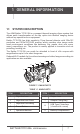
1.2 STANDARD COMPONENTS The Rattler standard components are shown in Figure 1-2 and listed in Table 1-2. The ITEM column indicates the number used to identify items in Figure 1-2. 1 5 4 6 2 3 FIGURE 1-2. STANDARD COMPONENTS TABLE 1-2. STANDARD COMPONENTS ITEM DESCRIPTION QUANTITY 1 Rattler Thermal Imaging Clip-On system 1 2 Objective Lens Cap 1 3 USB Cable 2 4 Lens Tissue 1 5 User Manual 1 6 Carrying Case 1 1.
TABLE 1-3. OPTIONAL EQUIPMENT ITEM DESCRIPTION PART NO. 1 AGM-2113 ADM Short QR Mount for Rattler 6306LSR1 2 Eyepiece for Rattler TC 6328ERC1 Front Q-R adapter for Rattler TC: ARM52-56 6306RC61 Front Q-R adapter for Rattler TC: ARM52-50 6306RC51 Front Q-R adapter for Rattler TC: ARM52-44 6306RC41 3 Front Q-R adapter for Rattler TC: ARM52-30 6306RC31 4 AGM Power Bank 6308EPB1 5 Hard Case for Storage/Transportation 6610HCS1 1.
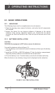
2 OPERATING INSTRUCTIONS 2.1. BASIC OPERATIONS 2.1.1 UNPACKING The following steps must be completed prior to each mission. 1. Open the carrying case, remove the device, and verify that all components are included. 2. Inspect the device for any obvious evidence of damage to the optical surfaces, body, eyecup, operation buttons, etc. Ensure that all optical surfaces are clean and ready for use. Clean all optical surfaces with a lens tissue. 2.1.
2.1.3 SELECT BATTERY TYPE You can change the battery type according to your need. Select the correct battery voltage in the device menu. 1. In the view mode, hold button to show the menu. 2. Select Battery Voltage menu item, and press button to switch the voltage. 2.1.4 CONNECTING THE DEVICE WARNING: Please remove the batteries from the battery compartment before connecting the device to your PC, or it may cause computer damage. FIGURE 2-2. CABLE INTERFACE 1. Open the cable interface cover. 2.
TABLE 2-1. BUTTON FUNCTIONS BUTTON 2.1.6 FUNCTIONS POWER Press: Sleep Mode/Wake Up Device Hold: Power On/Off MENU / SELECT Press: Enable/Disable OSD Hold: Menu Operation MODE / LEFT Press: Switch Palettes Hold: Enable/Disable PIP CAPTURE / UP Press: Capture Hold: Start/Stop Record Video SHUTTER / RIGHT Press: Correct Non-uniformity of Display CALIBRATION / DOWN Press with Capture button together to launch the Image Calibration menu.
2.1.8 THERMAL VIEW OBSERVATION 1. Install the Rattler TC on the weapon with a day scope (refer to part 2.1.15 or 2.1.16). Verify that the Rattler TC is securely mounted. 2. Remove the protective caps. 3. Point the equipment at an object. 4. Activate the Rattler TC. After approximately 4 sec, video of the thermal scene should appear. 5. If the day scope includes a focusing ring (i.e., parallax adjustment knob), adjust the focus for a parallax-free image. 6.
2.1.12 VIDEO RECORDING / IMAGE CAPTURE Video Recording Hold button in the view mode and start recording. In the upper left corner, the recording time displays. Hold button again to stop recording. FIGURE 2-5. VIDEO RECORDING Image Capturing Press button in the view mode, to capture the image. NOTE: • When captured, the image freezes for 1 second and a prompt shows on the display. • For exporting captured images, refer to File Export. 2.1.
2.1.14 IMAGE CALIBRATION Press and buttons together in the view mode to display the Image Calibration menu. Use Image Calibration to solve the problem of shooting deviation and to achieve better accuracy. For more information on Image Calibration procedures, see Part 2.2.8. 2.1.15 INSTALLING THE CLIP-ON ONTO THE LENS OF A DAY SCOPE WARNING: Always make sure your firearm is unloaded before you place the scope on the firearm. Reconfirm that the chamber is empty if you stop the procedure then resume later.
NOTE: Different models of front adapters may have different designs. Refer to the user manual for your adapter for correct installation. Install the Rattler TC on the lens of a day scope as follows (refer to Figure 2-7): 1. Turn the lever (A) of adapter (B) backwards to loosen the adapter clamping device. 2. Slide the Rattler TC with the adapter onto the lens of the day scope (C) as far as it goes. 3. Affix the clip-on to the day scope by locking the lever (A) of adapter. 4.
To install the Rattler TC on a Picatinny/Weaver rail, perform the following (Figure 2-9): 1. Unlock the clamping device of the scope mount by pushing down on the lever holder (A) and unlocking the lever (B). 2. Install the scope on the Picatinny/ Weaver rail so that the stop (C) slides into the transverse slot on the rail. 3. Affix the scope to the rail by locking the lever (B). 4. Verify that the clamping device is firmly holding the Rattler. If necessary, adjust the clamping device’s lever-cam lock.
5. If the day scope includes a focusing ring (i.e., parallax adjustment knob), adjust the focus for a parallax-free image. 6. Turn on the day scope’s reticle illumination and adjust the reticle brightness. 7. Adjust the focus of Rattler TC by turning the focus ring. 8. Using the buttons on the control panel, configure the Rattler TC for your specific situation. Set palette, brightness, contrast, scene mode and FFC (Flat Field Correction), to display the best image effect.
2.2 MAIN FUNCTIONS 2.2.1 MENU OPERATION When the device powers on, hold button in the view mode for 4 seconds to display the menu. Press and buttons to move between menu items. The active element is highlighted in orange. Press button to select menu item or change an option. Hold button to save settings and exit the menu. FIGURE 2-11. MAIN MENU TABLE 2-4. MENU FUNCTION MENU ITEM SYMBOL BATTERY VOLTAGE NETWORK OPTION FUNCTION Select the battery voltage. 3.0 V / 3.
MENU ITEM SYMBOL OPTION FUNCTION OFF ON Turn on and off the CVBS Output function to view the video on CVBS monitor. --- Correct dead pixel manually. CVBS DPC BURN PREVENTION ON OFF Turn on and off the Burn Prevention function. VERSION --- View the firmware version number and serial number. RESTORE --- Restore the device to defaults. AUTO POWER OFF OFF/30 min/ 45 min LANGUAGE 17 Languages TRAJECTORY 5 Profiles TIME SYNC.
1. Hold 2. Select button to show the menu. menu item to enable Wi-Fi hotspot function. 3. Turn on the WLAN and connect to the Wi-Fi hotspot. - Hotspot Name: Wlan-IPTS Serial No. - Hotspot Password: Last 9 digits of Serial No. 4. Search T-Vision client software on App Store (iOS System) or Google PlayTM (Android System) to download and install the app. 5. Run the app and connect your phone or tablet with the device. You can view the interface of clip-on on your phone.
2.2.8 ELECTRONIC ACCURACY CORRECTION After mounting of clip-on to the weapon with day scope the clip-on optical axis can be offset off scope optical axis. The Image Calibration function supports manually adjusting the position of the live preview window by pressing the buttons up, down, left, and right. The image region could be adjusted in 4 directions in the whole OLED screen area. X=0, Y=0 X=+68, Y=+58 FIGURE 2-12. IMAGE CORRECTION Adjust the electronic accuracy correction as follows: 1.
Manual: Press button in live view to correct the non-uniformity of display. External: Cover the lens cap, then press non-uniformity of display. 3. Hold button in live view to correct the button to confirm the setting and exit. 2.2.10 CVBS OUTPUT You can view the video on CVBS monitor, to get a better and clear image, more convenient to check the detail. 1. Connect the USB-CVBS cable to USB port of thermal clip-on and to monitor’s CVBS port. NOTE: USB-CVBS cable need to be purchase separately.
2.2.14 RESTORE DEVICE You can reset the settings of device. 1. Hold button to show the menu of device. Restore menu item and press 2. Select defaults according to the prompt. button to restore the device to 2.2.15 AUTO POWER OFF You can set the time for the automatic shutdown of the device as required. 1. Hold button to show the menu of device. Auto Power Off menu item and press 2. Select 30 min or 45 min. button to select OFF, 2.2.
1. Hold button to show the menu. 2. Select mode. menu item and press button to enter the Distance Measurement 3. Press button to go to the target setting interface. or to select the target from Wolf (0.8 m), Bear (3.0 m), Deer 1) Press (1.2 m), and Custom (1.8 m). Each target preset can be modified from 0.1 to 9.9 m. 2) Set the target and press button to confirm. 4. Align the center of top mark with the edge of target top. Press button. The cursor blinks on the top edge of the target. FIGURE 2-13.
2.3 CLIENT SOFTWARE INTRODUCTION Install T-Vision client software on your mobile phone first, and then connect your phone to the hotspot of the clip-on. Refer to chapter 2.2.3 for details of hotspot connection. NOTE: The device password is set by user at first activation. If the password was lost or forgotten, it can be reset. To make a reset, provide the following action: 1. When the clip-on is turned on, hold button to activate the OSD menu. menu item and press 2. Select default settings.
3 MAINTENANCE 3.1 MAINTENANCE 3.1.1 CLEANING PROCEDURES 1. Gently brush off any dirt from the body of the device using a clean, soft cloth. 2. Moisten the cloth with fresh water and gently wipe down the external surfaces (except lenses). 3. Dry any wet surfaces (except lenses) using another dry, clean, soft cloth. 4. Using a lens brush, carefully remove all loose dirt from the lenses. 5. Use a high quality lens wipe to remove dirt or smudges from the lens and display window.
6. Turn off the device. 7. Turn on the device. After a while, the firmware update process will start automatically. During the update, the screen will display the inscription “Upgrading ...”. The update process will be completed when the word “Upgrading ...” goes out. Repeat steps 5-7 for each updating file. 3.2 TROUBLESHOOTING Table 3-1 lists the most common malfunctions that may occur with your equipment. This table does not list all the malfunctions that may occur with your device.
4 WARRANTY INFORMATION 4.1 WARRANTY INFORMATION AND REGISTRATION 4.1.1 WARRANTY INFORMATION This product is guaranteed to be free from manufacturing defects in material and workmanship under normal use for a period of three (3) years from the date of purchase.
the Customer; AGM Global Vision’s obligations under this Agreement extend solely to the Customer. AGM Global Vision’s liability hereunder for damages, regardless of the form or action, shall not exceed the fees or other charges paid to AGM Global Vision by the customer or customer’s dealer.
5 SPECIFICATIONS 5.
AGM Global Vision, LLC MAIN OFFICE 173 West Main Street PO Box 962 Springerville, AZ 85938 USA Tel. +1.928.333.4300 info@agmglobalvision.com www.agmglobalvision.com EUROPEAN OFFICE #6 Andrey Lyapchev Blvd Sofia, P.C. 1756 Bulgaria Tel. +35.988.412.5573 info@agmglobalvision.eu www.agmglobalvision.eu AGMglobalvision.