Service Guide 3DUW 1XPEHU ( $SULO )RU :DUUDQW\ LQIRUPDWLRQ UHIHU WR WKH EDFN RI WKH PDQXDO &RS\ULJKW $JLOHQW 7HFKQRORJLHV ,QF $OO 5LJKWV 5HVHUYHG $JLOHQW ( $ '& 3RZHU 6XSSO\
The Agilent Technologies E3631A is a high performance 80 watt-triple output DC power supply with GPIB and RS-232 interfaces. The combination of benchtop and system features in this power supply provides versatile solutions for your design and test requirements.
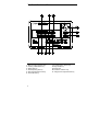
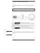
The Front Panel at a Glance 1 2 3 4 5 6 2 Meter and adjust selection keys Tracking enable/disable key Display limit key Recall operating state key Store operating state/Local key Error/Calibrate key 7 I/O Configuration / Secure key 8 Output On/Off key 9 Control knob 10 Resolution selection keys 11 Voltage/current adjust selection key
1 Meter and adjust selection keys Select the output voltage and current of any one supply (+6V, +25V, or -25V output) to be monitored on the display and allow knob adjustment of that supply. 2 Tracking enable / disable key Enables / disables the track mode of ±25V supplies. 3 Display limit key Shows the voltage and current limit values on the display and allows knob adjustment for setting limit values. 4 Recall operating state key Recalls a previously stored operating state from location "1", "2", or "3".
Front-Panel Voltage and Current Settings You can set the voltage and current from the front panel using the following method. Use the voltage/current adjust selection key, the resolution selection keys, and the control knob to change the limiting or limitings value of voltage or current. 1 Press the Display Limit key after turning on the power supply. 2 Set the knob to the voltage control mode or current control mode using the voltage/ current adjust selection key.
Display Annunciators Adrs Power supply is addressed to listen or talk over a remote interface. Rmt Power supply is in remote interface mode. +6V Displays the output voltage and current for +6V supply. Knob is active for +6V supply. +25V Displays the output voltage and current for +25V supply. Knob is active for +25V supply. -25V Displays the output voltage and current for -25V supply. Knob is active for -25V supply. CAL power supply is in calibration mode.
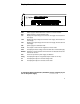
The Rear Panel at a Glance 1 Power-line voltage setting 2 Power-line fuse-holder assembly 3 AC inlet Use the front-panel I/O Config 4 Power-line module 5 GPIB (IEEE-488) interface connector 6 RS-232 interface connector key to: • Select the GPIB or RS-232 interface (see chapter 3). • Set the GPIB bus address (see chapter 3). • Set the RS-232 baud rate and parity (see chapter 3).
In This Book Specifications Chapter 1 lists the power supply’s specifications and describes how to interpret these specifications. Quick Start Chapter 2 prepares the power supply for use and helps you get familiar with the front-panel features. Calibration Procedures Chapter 3 provides performance verification and calibration procedures. Theory of Operation Chapter 4 describes block and circuit level theory related to the operation of the power supply.
8
Contents Chapter 1 Specifications Performance Specifications - - - - - - - - - - - - - - - - - - - - - - - - - - - - - 15 Supplemental Characteristics - - - - - - - - - - - - - - - - - - - - - - - - - - - 17 Chapter 2 Quick Start To prepare the power supply for use - - - - - - - - - - - - - - - - - - - - - To check the rated voltages of the power supply - - - - - - - - - - - To check the rated currents of the power supply - - - - - - - - - - - To use the power supply in constant voltage mode - - - - - - -
Contents Chapter 3 Calibration Procedures (continued) Constant Current (CC) Verifications - - - - - - - - - - - - - - - - - - - - - - 54 Constant Current Test Setup - - - - - - - - - - - - - - - - - - - - - - - - - - - 54 Current Programming and Readback Accuracy - - - - - - - - - - - - 54 CC Load Regulation - - - - - - - - - - - - - - - - - - - - - - - - - - - - - - - - - - 56 CC Line Regulation - - - - - - - - - - - - - - - - - - - - - - - - - - - - - - - - - - - 57 Normal Mode Current Noise (CC Ripple a
Contents Chapter 5 Service (continued) Repacking for Shipment - - - - - - - - - - - - - - - - - - - - - - - - - - - - - - - Electrostatic Discharge (ESD) Precautions - - - - - - - - - - - - - - - Surface Mount Repair - - - - - - - - - - - - - - - - - - - - - - - - - - - - - - - - - To Replace the Power-Line Fuse - - - - - - - - - - - - - - - - - - - - - - - - Troubleshooting Hints - - - - - - - - - - - - - - - - - - - - - - - - - - - - - - - - Unit is Inoperative - - - - - - - - - - - - - - - - - - - - - -
Contents 12
1 1 Specifications
Specifications The performance specifications are listed in the following pages. Specifications are warranted in the temperature range of 0 to 40°C with a resistive load. Supplemental characteristics, which are not warranted but are descriptions of performance determined either by design or testing. Chapter 3 "Calibration Procedures" contains procedures for verifying the performance specifications. All specifications apply to the three outputs unless otherwise specified.
Chapter 1 Specifications Performance Specifications 1 Performance Specifications Output Ratings (@ 0°C - 40°C) +6V Output 0 to +6 V ; 0 to 5 A +25V Output 0 to +25 V ; 0 to 1 A -25V Output 0 to -25 V ; 0 to 1 A Programming Accuracy [1] 12 months (@ 25°C ± 5°C), ±(% of output + offset) +6V Output +25V Output -25V Output Voltage 0.1% + 5 mV 0.05% + 20 mV 0.05% + 20 mV Current 0.2% + 10 mA 0.15% + 4 mA 0.
Chapter 1 Specifications Performance Specifications Programming Resolution +6V Output Voltage 0.5 mV Current 0.5 mA +25V Output 1.5 mV 0.1 mA -25V Output 1.5 mV 0.1 mA Readback Resolution +6V Output Voltage 0.5 mV Current 0.5 mA +25V Output 1.5 mV 0.1 mA -25V Output 1.5 mV 0.
Chapter 1 Specifications Supplemental Characteristics 1 Supplemental Characteristics Output Programming Range (maximum programmable values) +25V Output -25V Output +6V Output Voltage 0 to 6.18 V 0 to 25.75 V 0 to -25.75 V Current 0 to 5.15 A 0 to 1.03 A 0 to 1.03 A Temperature Coefficient, ±(% of output + offset) Maximum change in output/readback per °C after a 30-minute warm-up +25V Output -25V Output +6V Output Voltage 0.01% + 2 mV 0.01% + 3 mV 0.01% + 3 mV Current 0.02% + 3 mA 0.02% + 0.5 mA 0.02% + 0.
Chapter 1 Specifications Supplemental Characteristics Cooling Fan cooled Operating Temperature 0 to 40°C for full rated output. At higher temperatures, the output current is derated linearly to 50% at 55°C maximum temperature. Output Voltage Overshoot During turn-on or turn-off of ac power, output plus overshoot will not exceed 1 V if the output control is set to less than 1 V. If the output control is set to 1 V or higher, there is no overshoot.
Chapter 1 Specifications Supplemental Characteristics 1 Figure 1-1.
Chapter 1 Specifications Supplemental Characteristics 20
2 2 Quick Start
Quick Start One of the first things you will want to do with your power supply is to become acquainted with its front panel. Written procedures in this chapter prepare the power supply for use and familiarize you with most front-panel operations. • The power supply is shipped from the factory configured in the front-panel operation mode. At power-on, the power supply is automatically set to operate in the front-panel operation mode. When in this mode, the frontpanel keys can be used.
Chapter 2 Quick Start To prepare the power supply for use To prepare the power supply for use The following steps help you verify that the power supply is ready for use. 1 Check the list of supplied items. Verify that you have received the following items with your power supply. If anything is missing, contact your nearest Agilent Technologies Sales Office. One appropriate power cord for your location. One User's Guide. This Service Guide. Certificate of Calibration.
Chapter 2 Quick Start To prepare the power supply for use 1 Remove the power cord. Remove the fuse-holder assembly with a flat-blade screwdriver from the rear panel. 2 Install the corect line fuse. Remove the power-line voltage selector from the power-line 100 or 115 Vac, 2.5 AT fuse 230 Vac, 2 AT fuse 3 Rotate the power-line voltage selector until the correct voltage appears. 4 Replace the power-line voltage selector and the fuse-holder assembly in the rear panel.
Chapter 2 Quick Start To check the rated voltages of the power supply To check the rated voltages of the power supply The following procedures check to ensure that the power supply develops its rated voltage outputs with no load and properly responds to operation from the front panel. For each step, use the keys shown on the left margins. Power 1 Turn on the power supply.
Chapter 2 Quick Start To check the rated voltages of the power supply +25V 5 Check the voltage function for the +25V supply. Select the meter and adjust selection key for the +25V supply. The CV annunciator is still lit and the +25V annunciator will turn on. Repeat steps (3) and (4) to check the voltage function for the +25V supply. -25V 6 Check the voltage function for the -25V supply. Select the meter and adjust selection key for the -25V supply.
Chapter 2 Quick Start To check the rated currents of the power supply To check the rated currents of the power supply The following procedures check to ensure that the power supply develops its rated current outputs with a short and properly responds to operation from the front panel. For each step, use the keys shown on the left margin. Power 1 Turn on the power supply.
Chapter 2 Quick Start To check the rated currents of the power supply 6 Ensure that the current can be adjusted from zero to the maximum 1 rated value. Adjust the knob until the ammeter indicates 0 amps and then until the ammeter indicates 5.0 amps. +25V 7 Check the current function for the +25V supply. Disable the outputs by pressing the Output On/Off key and connect a short across (+) and (COM) output terminals of the ±25V supply with an insulated test lead.
Chapter 2 Quick Start To use the power supply in constant voltage mode To use the power supply in constant voltage mode To set up the power supply for constant voltage (CV) operation, proceed as follows. For each step, use the keys shown on the left margin. 1 Connect a load to the desired output terminals. With power-off, connect a load to the desired output terminals. Power 2 Turn on the power supply.
Chapter 2 Quick Start To use the power supply in constant voltage mode Vol/Cur 5 Adjust the knob for the desired current limit. 1 Check that the Lmt annunciator still blinks. Set the knob for current control. The second digit of ammeter will be blinking. Adjust the knob to the desired current limit. Vol/Cur 6 Adjust the knob for the desired output voltage. 1 Set the knob for voltage control. The second digit of the voltmeter will be blinking. Adjust the knob to the desired output voltage.
Chapter 2 Quick Start To use the power supply in constant current mode To use the power supply in constant current mode To set up the power supply for constant current (CC) operation, proceed as follows. For each step, use the keys shown on the left margin. 1 Connect a load to the output terminals of the desired supply. With power-off, connect a load to the desired output terminals. Power 2 Turn on the power supply.
Chapter 2 Quick Start To use the power supply in constant current mode 5 Adjust the knob for the desired voltage limit. 1 Check that the knob is still selected for voltage control and the Lmt annunciator blinks. Adjust the knob for the desired voltage limit. Vol/Cur 6 Adjust the knob for the desired output current. 1 Set the knob for current control. The second digit of the ammeter will be blinking. Adjust the knob to the desired current output. Display Limit 7 Return to the meter mode.
Chapter 2 Quick Start To use the power supply in track mode To use the power supply in track mode The ±25V supplies provide 0 to ±25 V tracking outputs. In the track mode, two voltages of the ±25V supplies track each other to within ±(0.2% of output + 20 mV) for convenience in varying the symmetrical voltages needed by operational amplifiers and other circuits using balanced positive and negative inputs.
Chapter 2 Quick Start To store and recall the instrument state To store and recall the instrument state You can store up to three different operating states in non-volatile memory. This also enables you to recall the entire instrument state with just a few key presses from the front panel.
Chapter 2 Quick Start To store and recall the instrument state Store 4 Save the operating state. The operating state is now stored. To recall the stored state, go to the following steps. 2 done This message appears on the display for approximately 1 second. Recall 5 Turn on the recall mode. Memory location "1" will be displayed in the recall mode. recall 1 This message appears on the display for approximately 3 seconds. 6 Recall the stored operating state.
Chapter 2 Quick Start To rack mount the power supply To rack mount the power supply The power supply can be mounted in a standard 19-inch rack cabinet using one of three optional kits available. A rack-mounting kit for a single instrument is available as Option 1CM (P/N 5062-3957). Installation instructions and hardware are included with each rack-mounting kit. Any Agilent Technologies System II instrument of the same size can be rack-mounted beside the Agilent E3631A power supply.
Chapter 2 Quick Start To rack mount the power supply 2 To rack mount two instruments of the same depth side-by-side, order lock-link kit 5061-9694 and flange kit 5063-9214. To install two instruments in a sliding support shelf, order suport shelf 50639256, and slide kit 1494-0015.
Chapter 2 Quick Start To rack mount the power supply 38
3 Calibration Procedures
Calibration Procedures This chapter contains procedures for verification of the power supply's performance and calibration (adjustment).
Chapter 3 Calibration Procedures Agilent Technologies Calibration Services Closed-Case Electronic Calibration The power supply features closedcase electronic calibration since no internal mechanical adjustments are required for normal calibration. The power supply calculates correction factors based upon the input reference value you enter. The new correction factors are stored in non-volatile memory until the next calibration adjustment is performed.
Chapter 3 Calibration Procedures Automating Calibration Procedures Automating Calibration Procedures You can automate the complete verification procedures outlined in this chapter if you have access to programmable test equipment. You can program the instrument configurations specified for each test over the remote interface. You can then enter readback verification data into a test program and compare the results to the appropriate test limit values.
Chapter 3 Calibration Procedures Test Considerations Test Considerations To ensure proper instrument operation, verify that you have selected the correct power-line voltage prior to attempting any test procedure in this chapter. See page 24 in chapter 2 for more information. • Assure that the calibration ambient temperature is stable and between 20°C and 30°C. • Assure ambient relative humidity is less than 80%. • Allow a 1-hour warm-up period before verification or calibration.
Chapter 3 Calibration Procedures Performance Verification Tests Performance Verification Tests The performance verification tests use the power supply's specifications listed in chapter 1, "Specifications", starting on page 13. You can perform two different levels of performance verification tests: • Self-Test A series of internal verification tests that provide high confidence that the power supply is operational.
Chapter 3 Calibration Procedures Measurement Techniques Measurement Techniques Setup for Most Tests Most tests are performed at the front terminals as shown in the following figure. Measure the dc voltage directly at the (+) and (-) terminals on the front panel. 3 Figure 3-1. Performance Verification Test Setup Electronic Load Many of the test procedures require the use of a variable load resistor capable of dissipating the required power.
Chapter 3 Calibration Procedures Measurement Techniques load resistor is plugged into the front of the output terminals at (B). A measurement made across the load includes the impedance of the leads to the load. The impedance of the load leads can easily be several orders of the magnitude greater than the power supply impedance and thus invalidate the measurement. To avoid mutual coupling effects, each measuring device must be connected directly to the output terminals by separate pairs of leads.
Chapter 3 Calibration Procedures Constant Voltage (CV) Verifications Constant Voltage (CV) Verifications Constant Voltage Test Setup If more than one meter or a meter and an oscilloscope are used, connect each to the (+) and (-) terminals by a separate pair of leads to avoid mutual coupling effects. Use coaxial cable or shielded 2-wire cable to avoid noise pick-up on the test leads.
Chapter 3 Calibration Procedures Constant Voltage (CV) Verifications 5 Readback the output voltage of the selected output over the remote interface by sending the command: MEAS:VOLT? {P6V|P25V|N25V} 6 Record the value displayed on the controller. This value should be within the limits specified below for each output tested. Output Programming Accuracy DVM ± 5 mV +6V +25V DVM ± 10 mV -25V -(DVM ± 10 mV) 7 Program the selected output's voltage to full scale value by sending the commands. VOLT 6.
Chapter 3 Calibration Procedures Constant Voltage (CV) Verifications CV Load Regulation This test measures the change in the output voltage resulting from a change in the output current from full to no load. 1 Turn off the power supply and connect a digital voltmeter between the (+) and (-) terminals of the output to be tested as shown in Figure 3-1. 2 Turn on the power supply and select the desired output to be tested using the meter and adjust selection key on the front panel.
Chapter 3 Calibration Procedures Constant Voltage (CV) Verifications CV Line Regulation This test measures the change in output voltage that results from a change in ac line voltage from the minimum value (10% below the nominal input voltage) to maximum value (10% above the nominal input voltage). 1 Turn off the power supply and connect a digital voltmeter between the (+) and (-) terminals of the output to be tested as shown in Figure 3-1. 2 Connect the ac power line through a variable voltage transformer.
Chapter 3 Calibration Procedures Constant Voltage (CV) Verifications Normal Mode Voltage Noise (CV Ripple and Noise) The normal mode voltage noise is in the form of ripple related to the line frequency plus some random noise. The normal mode voltage noise is specified as the rms or peak-to-peak output voltage in a frequency range from 20 Hz to 20 MHz. 1 Turn off the power supply and connect the output to be tested as shown in Figure 3-1 to an oscilloscope (ac coupled) between (+) and (-) terminals.
Chapter 3 Calibration Procedures Constant Voltage (CV) Verifications Common Mode Current Noise The common mode current is that ac current component which exists between any or all outputs or output lines and chassis ground. Common mode noise can be a problem for very sensitive circuitry that is referenced to earth ground. When a circuit is referenced to earth ground, a low level line-related ac current will flow from the output terminals to earth ground.
Chapter 3 Calibration Procedures Constant Voltage (CV) Verifications Load Transient Response Time This test measures the time for the output voltage to recover to within 15 mV of nominal output voltage following a load change from full load to half load, or half load to full load. 1 Turn off the power supply and connect the output to be tested as shown in Figure 3-1 with an oscilloscope. Operate the electronic load in constant current mode.
Chapter 3 Calibration Procedures Constant Current (CC) Verifications Constant Current (CC) Verifications Constant Current Test Setup Follow the general setup instructions in the "Measurement Techniques" section starting on page 45 and the specific instructions will be given in the following paragraphs. Current Programming and Readback Accuracy This test verifies that the current programming and GPIB or RS-232 readback functions are within specifications.
Chapter 3 Calibration Procedures Constant Current (CC) Verifications 5 Readback the output current from the selected output over the remote interface by sending the command: MEAS:CURR? {P6V|P25V|N25V} 6 Record the value displayed on the controller. This value should be within the limits specified below for each output tested.
Chapter 3 Calibration Procedures Constant Current (CC) Verifications CC Load Regulation This test measures the change in output current resulting from a change in the load from full-scale output voltage to short circuit. 1 Turn off the power supply and connect the output to tested as shown in Figure 3-1 with the digital voltmeter connected across the 0.19 current monitoring resistor (RM).
Chapter 3 Calibration Procedures Constant Current (CC) Verifications CC Line Regulation This test measures the change in output current that results from a change in ac line voltage from the minimum value (10% below the nominal input voltage) to the maximum value (10% above nominal voltage). 1 Turn off the power supply and connect the output to be tested as shown in Figure 3-1 with the digital voltmeter connected across the current monitoring resistor (RM).
Chapter 3 Calibration Procedures Constant Current (CC) Verifications Normal Mode Current Noise (CC Ripple and Noise) The normal mode current noise is specified as the rms output current in a frequency range 20 Hz to 20 MHz with the power supply in constant current operation. 1 Turn off the power supply and connect the output to be tested as shown in Figure 3-1 with a load resistor (1.29 for +6V supply and 259 for ±25V supplies) across output terminals to be tested.
Chapter 3 Calibration Procedures Performance Test Record for Agilent E3631A Performance Test Record for Agilent E3631A CV Performance Test Record Test Description Actual Result Specifications Upper Limit Lower Limit CV Programming Accuracy @ 0 volts (DVM reading) +6V supply +25V supply -25V supply +0.0050 V +0.0200 V +0.0200 V CV Readback Accuracy @ 0 volts +6V supply +25V supply -25V supply DVM + 0.0050 V DVM - 0.0050 V DVM + 0.0100 V DVM - 0.0100 V -(DVM + 0.0100) V -(DVM - 0.
Chapter 3 Calibration Procedures Performance Test Record for Agilent E3631A CC Performance Test Record Test Description Actual Result Specifications Upper Limit Lower Limit CC Programming Accuracy @ 0 amps (IO) +6V supply +25V supply -25V supply +0.0100 A +0.0040 A +0.0040 A -0.0100 A -0.0040 A -0.0040 A CC Readback Accuracy @ 0 amps +6V supply +25V supply -25V supply IO + 0.0100 A IO + 0.0040 A IO + 0.0040 A IO - 0.0100 A IO - 0.0040 A IO - 0.
Chapter 3 Calibration Procedures Calibration Security Code Calibration Security Code This feature allows you to enter a security code (electronic key) to prevent accidental or unauthorized calibrations of the power supply. When you first receive your power supply, it is secured. Before you can calibrate the power supply, you must unsecure it by entering the correct security code. A procedure to unsecure the power supply is given on the following page.
Chapter 3 Calibration Procedures Calibration Security Code To Unsecure the Power Supply for Calibration The power supply can use a calibration security code to prevent unauthorized or accidental calibration. This procedure shows you how to unsecure the power supply for calibration from the front panel. Calibrate Power 1 Turn on the front-panel calibration mode.
Chapter 3 Calibration Procedures Calibration Security Code Secure 4 Unsecure the power supply. unsecured The power supply is unsecured when you press the Secure key. You will see the above message from the front panel for one second. The "CAL MODE" message is displayed on the front panel after above message. Power 5 Turn off the calibration mode. 3 Turn off the power supply to exit the calibration mode. To re-secure the power supply (following calibration), perform this procedure again.
Chapter 3 Calibration Procedures Calibration Security Code To Unsecure the Power Supply Without the Security Code To unsecure the power supply without the correct security code (when you forget the security code), follow the steps below. See "Electrostatic Discharge (ESD) Precautions" in chapter 5 before beginning this procedure. 1 Disconnect the power cord and all load connections from front terminals. 2 Remove the instrument cover. Refer to the disassembly drawing on page 123.
Chapter 3 Calibration Procedures Calibration Count Calibration Count The calibration count feature provides an independent "serialization" of your calibrations. You can determine the number of times that your power supply has been calibrated. By monitoring the calibration count, you can determine whether an unauthorized calibration has been performed. Since the value increments by one for each calibration parameter (see Table 3-3 on the next page), a complete calibration increases the value by 6 counts.
Chapter 3 Calibration Procedures General Calibration/Adjustment Procedure General Calibration/Adjustment Procedure The calibration procedures from the front panel are described in this section. For output voltage calibration, disconnect all loads from the power supply and connect a DVM across the output terminals to be calibrated.
Chapter 3 Calibration Procedures General Calibration/Adjustment Procedure To calibrate the output voltages and currents of the power supply from the front panel, proceed as follows: 1 Unsecure the power supply. To calibrate the output voltage and current, you must unsecure the power supply according to the procedure given on page 62. 2 Disconnect all loads from the power supply and connect a DVM across output terminals of the +6V output. Calibrate 3 Turn on the calibration mode.
Chapter 3 Calibration Procedures General Calibration/Adjustment Procedure Calibrate 7 Pressing the "Calibrate" key saves the change and selects the second voltage calibration point for the +6V supply. v hi +5.7000v If the entered number is within an acceptable range, an "ENTERED" message appears for one second. The display now shows the second voltage calibration point for the +6V supply.
Chapter 3 Calibration Procedures General Calibration/Adjustment Procedure Connect an appropriate shunt (see Table 3-1 on page 42) across the +6V supply's output terminals, and connect a digital voltmeter across the shunt resistor for the current calibration. Calibrate 10 Select the first current calibration point for the +6V supply. i lo +0.100 a 3 The display shows the first current calibration point for the +6V supply.
Chapter 3 Calibration Procedures General Calibration/Adjustment Procedure 13 Read the DVM and change the second current value on the display to match the computed current (DVM reading ¸ by shunt resistance). For example, if the computed value is 4.999 A, adjust the current to 4.999 A using the knob and arrow keys. Notice that you should wait for the DVM reading to stabilize for accurate calibration. i hi +4.
Chapter 3 Calibration Procedures Aborting a Calibration in Progress Aborting a Calibration in Progress Sometimes it may be necessary to abort a calibration after the procedure has already been initiated. You can abort a calibration at any time by turning the power supply off from the front panel. When performing a calibration from the remote interface, you can abort a calibration by issuing a remote interface device clear message or by pressing the front-panel "Local" key.
Chapter 3 Calibration Procedures Calibration Record for Agilent E3631A Calibration Record for Agilent E3631A Step Calibration Description 1 Unsecure the power supply (see page 62). 2 Turn on "CAL MODE"(simultaneously press "Calibrate" and "Power" keys) until a beep is heard. Measurement Mode (DVM) Supply being Adjusted 3 Move down menu to "CAL SETUP 1" (press "Calibrate" key). 4 "V LO 0.1000 V" appears on the display (change the display to match the DVM reading; then press ``Calibrate'' key).
Chapter 3 Calibration Procedures Error Messages Error Messages The following tables are abbreviated lists of error messages for the E3631A. The errors listed are the most likely errors to be encountered during calibration and adjustment. A more complete list of error messages and descriptions is contained in chapter 5 of the E3631A User's Guide.
Chapter 3 Calibration Procedures Error Messages Calibration Error Messages Error Error Message 701 702 703 704 708 711 712 713 740 741 742 743 744 745 746 747 748 Cal security disabled by jumper Cal secured Invalid secure code Secure code too long Cal output disabled Cal sequence interrupted Bad DAC cal data Bad readback cal data Cal checksum failed, secure state Cal checksum failed, string data Cal checksum failed, store/recall data in location 1 Cal checksum failed, store/recall data in location 2 Cal
Chapter 3 Calibration Procedures Calibration Program Calibration Program This section contains an Agilent BASIC program for calibration over the GPIB interface. This program makes software adjustments to the E3631A power supply using a current shunt and a digital mutimeter which is connected to the controller. In this program a 0.01 ohm current shunt is used.
Chapter 3 Calibration Procedures Calibration Program ...continued 400 410 420 430 440 450 460 470 480 490 500 510 520 530 540 550 560 570 580 590 600 610 620 630 640 650 660 670 680 690 700 710 720 730 740 750 760 770 780 790 800 810 820 830 840 850 860 870 880 890 900 PRINT TABXY(10,10),"*************************************************" PRINT TABXY(10,11)," Using the annunciator, note the output selected." PRINT TABXY(10,12)," Connect the selected output to the DMM.
Chapter 3 Calibration Procedures Calibration Program ...continued 910 920 930 940 950 960 970 980 990 1000 1010 1020 1030 1040 1050 1060 1070 1080 1090 1100 1110 1120 1130 1140 1150 1160 1170 1180 1190 1200 1210 1220 1230 1240 1250 1260 1270 1280 1290 1300 1310 1320 1330 1340 1350 1360 1370 1380 1390 1400 1410 1420 1430 PRINT TABXY(10,9),"***************************************************" PRINT TABXY(10,10)," Connect a CURRENT SHUNT to the Dmm for measuring" PRINT TABXY(59,10)," current.
Chapter 3 Calibration Procedures Calibration Program 78
4 4 Theory of Operation
Theory of Operation This chapter provides block diagram level descriptions of the power supply. The descriptions provide a basic understanding of circuit operation and are intended as an aid in troubleshooting. It is assumed in the following discussions that you are familiar with the operating and programming instructions presented in the E3631A User's Guide.
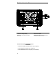
Chapter 4 Theory of Operation Block Diagram Overview Block Diagram Overview This discussion pertains to the block diagram on the next page. The power supply's circuitry is divided into two major blocks: the floating circuitry and the ground referenced circuitry. All power mesh and control circuits, display circuit, and digital circuits are contained in the floating circuitry. This circuitry also contains the power supply's main controller.
Chapter 4 Theory of Operation Block Diagram Overview Block Diagram FLOATING CIRCUITRY 82 EARTH REFERENCED CIRCUITRY
Chapter 4 Theory of Operation AC Input and Bias Supplies AC Input and Bias Supplies Referring to the schematic shown on page 127, the ac mains are connected by a fused power module. This module incorporates the functions of mains connection, fusing, and line voltage selection (100/115/230 Vac). The line voltage selection function of the module selects which primary winding of power transformer T1 is energized. The transformer secondary windings are connected to the main pc board through connectors.
Chapter 4 Theory of Operation Floating Logic Floating Logic Referring to the schematic shown on page 128, the floating common logic controls operation of the entire instrument. All output functions and bus command interpretation is performed in the main controller U17. The front panel and the earth referenced logic operate as slaves to U17.
Chapter 4 Theory of Operation Floating Logic The serial register is used to send and receive serial data bytes from the main controller to the DAC system, or to communicate with the front panel controller. The serial register is multiplexed to these two circuits. The transmission rate is selected to 1.5 M bits/second for the DAC system and 93.75 k bits/second for communication with the front panel controller. The general serial interface is a 3-bit interface as shown below.
Chapter 4 Theory of Operation D-to-A Converter D-to-A Converter Referring to the schematic shown on page 129, all reference voltages of power circuits are derived from the internal voltage reference of system DAC U12 on the top board. The system DAC track/hold amplifier outputs are used to provide controllable reference voltages to three power circuits. The system DAC is programmed and responds to the main controller via internal 3-wire serial data bus SERCLK, SERRBK, and SERSTB.
Chapter 4 Theory of Operation A-to-D Converter A-to-D Converter Referring to the schematic shown on page 129, the analog-to-digital converter (ADC) is used to change dc voltages into digital information. The circuitry consists of an integrator amplifier (U6 and U8), current steering switch U5, resistors (R5, R4, R15 and R16), voltage reference (U3A and U3B), ADC controller U16, and residue ADC U17 on the top board. The ADC method used by the Agilent E3631A is called multislope III.
Chapter 4 Theory of Operation Power Mesh and Control Power Mesh and Control Refer to the schematics shown on page 130 and page 131. For the ±25V power mesh and control circuit, a preregulator is added ahead of the series pass transistor to minimize the power dissipated in the series pass transistor by controlling the dc level across the input filter capacitor, depending on the output voltage.
Chapter 4 Theory of Operation Power Mesh and Control Two error amplifiers are included in a CV/CC supply, one for controlling output voltage, the other for controlling output current.
Chapter 4 Theory of Operation Earth-Referenced Logic Earth-Referenced Logic Referring to the schematic shown on page 132, the earth referenced logic circuits schematic provides all rear panel input/output capability. Microprocessor U10 on the bottom board handles GPIB (IEEE-488) control through bus interface chip U8 and bus receiver/driver chips U6 and U7 on the bottom board. The RS-232 interface is also controlled through microprocessor U10.
5 5 Service
Service This chapter discusses the procedures involved for returning a failed power supply to Agilent Technologies for service or repair.
Chapter 5 Service Operating Checklist Operating Checklist Before returning your power supply to Agilent Technologies for service or repair check the following items: Is the Power Supply Inoperative? Verify that the ac power cord is connected to the power supply. Verify that the front-panel power switch is depressed. Verify that the power-line fuse is installed: Use the 2.5 AT, 250 V fuse for 100 or 115 Vac operation. Use the 2 AT, 250 V fuse for 230 Vac operation. Verify the power-line voltage setting.
Chapter 5 Service Types of Service Available Types of Service Available If your power supply fails within three years of original purchase, Agilent Technologies will repair or replace it free of charge. If your unit fails after your three year warranty expires, Agilent will repair or replace it as a very competitive price. Agilent will make the decision locally whether to repair or replace your unit. Standard Repair Service (worldwide) Contact your nearest Agilent Technologies Service Center.
Chapter 5 Service Repacking for Shipment Repacking for Shipment For the Express Exchange Service described on the previous page, return your failed Agilent E3631A to the designated Agilent Service Center using the shipping carton of the exchange unit. A shipping label will be supplied. Agilent will notify you when your failed unit has been received.
Chapter 5 Service Electrostatic Discharge (ESD) Precautions Electrostatic Discharge (ESD) Precautions Almost all electrical components can be damaged by electrostatic discharge (ESD) during handling. Component damage can occur at electrostatic discharge voltages as low as 50 volts. The following guidelines will help prevent ESD damage when serving the power supply or any electronic device. • Disassemble instruments only in a static-free work area. • Use a conductive work area to dissipate static charge.
Chapter 5 Service Troubleshooting Hints Troubleshooting Hints This section provides a brief check list of common failures. Before troubleshooting or repairing the power supply, make sure that the failure is in the instrument rather than any external connections. Also make sure that the instrument is accurately calibrated. The power supply's circuits allow troubleshooting and repair with basic equipment such as a digit multimeter and a 100 MHz oscilloscope.
Chapter 5 Service Troubleshooting Hints Bias Supplies Problems Check that the input to the voltage regulators of the bias supplies is at least 1 V greater than their output. Circuit failures can cause heavy loads of the bias supplies which may pull down the regulator output voltages. Check the voltages of bias supplies as tabulated below. Table 5-1. Bias Supplies Voltages Bias Supply +5V Floating -5.
Chapter 5 Service Self-Test Procedures Self-Test Procedures Power-On Self-Test Each time the power supply is powered on, a set of self-tests are performed. These tests check that the minimum set of logic and measurement hardware are functioning properly. The power-on self-test performs checks 601 through 604 and 624 through 634. Complete Self-Test Hold any front panel key except the "Error'' key for more than 5 seconds while turning on the power to perform a complete self-test.
Chapter 5 Service Self-Test Procedures 605 Cannot calibrate rundown gain This test checks the nominal gain between integrating ADC and the U17 on-chip ADC. This error is reported if the procedure can not run to completion due to a hardware failure. 606 Rundown gain out of range This test checks the nominal gain between the integrating ADC and the U17 on-chip ADC. The nominal gain is checked to ±10% tolerance.
Chapter 5 Service Self-Test Procedures 632 P6V hardware test failed This test checks the the status of voltage and current error amplifiers for +6V power circuit. If both amplifiers are not operational, the power supply will beep and the error annunciator will be on. 633 P25V hardware test failed This test checks the the status of voltage and current error amplifiers for +25V power circuit. If both amplifiers are not operational, the power supply will beep and the error annunciator will be on.
Chapter 5 Service Self-Test Procedures 102
6 6 Replaceable Parts
Replaceable Parts 7KLV FKDSWHU FRQWDLQV LQIRUPDWLRQ RUGHULQJ UHSODFHPHQW SDUWV IRU \RXU SRZHU VXSSO\ 7KH SDUWV OLVWV DUH GLYLGHG LQWR WKH IROORZLQJ IRXU JURXSV 7RS 3&% $VVHPEO\ ( 9)' $VVHPEO\ ( %RWWRP 3&% $VVHPEO\ ( )URQW )UDPH $VVHPEO\ ( ( $ 3RZHU 6XSSO\ $VVHPEO\ 7KH WRS 3&% DVVHPEO\ ( LV FRPSRVHG RI 9 SRZHU FLUFXLWV 9 ELDV VXSSOLHV IRU 9 SRZHU FLUFXLWV 9 9 DQG 9 ELDV VXSSOLHV IORDWLQJ ORJLF '$& DQG $'&
Chapter 6 Replaceable Parts E3631-60002 Top PCB Assembly E3631-60002 Top PCB Assembly Reference Designator Agilent Part Number Qty Description Mfr Code Mfr Part Number C1-C2 0160-6497 26 CAP-FXD 0.1uF+-10% 50V CER X7R 04222 12065C104KAT A C3 0180-4116 2 CAP-FXD 22uF +-20% 20V TA 12340 T491D226M020AS C4-C5 0160-6497 CAP-FXD 0.1uF+-10% 50V CER X7R 04222 12065C104KAT A C6-C7 0160-6736 CAP-FXD 0.01uF +-10% 50V CER X7R 12340 C1206C103K5RAC C8-C9 0160-6497 CAP-FXD 0.
Chapter 6 Replaceable Parts E3631-60002 Top PCB Assembly Reference Designator Agilent Part Number Qty Description Mfr Code Mfr Part Number CR1-CR3 1906-0291 10 DIODE-DUAL 70V 100mA TO-236 AA 28480 1906-0291 CR4-CR6 1901-1149 13 DIODE-PWR RECT 400V 1A 50NS DO-41 71744 UF4004 CR7 1906-0351 2 DIODE-FW BRDG 200V 2A 71744 2KBP02M CR8-CR10 1906-0291 DIODE-DUAL 70V 100mA TO-236 AA 28480 1906-0291 CR11-CR12 1901-1227 11 DIODE-SWICHING 75V 200mA 6nS TO-236 27014 BAS16 CR13-CR14 1
Chapter 6 Replaceable Parts E3631-60002 Top PCB Assembly Reference Designator Agilent Part Number Qty Description Mfr Code Mfr Part Number F1-F2 0699-2715 2 RESISTOR-FUSE 1 OHM +-5% 0.5W @70 28480 0699-2715 R1 0699-1405 4 RESISTOR 38.3K +-1% .125W TKF TC=0+-100 2M627 MCR18FX R2-R3 0699-1385 2 RESISTOR 5.11K +-1% .125W TKF TC=0+-100 2M627 MCR18FX R4-R5 0699-2837 2 RESISTOR 30K +-0.1% .125W TF TC=0+-25 11502 W1206R033001BT R6-R8 0699-2489 3 RESISTOR 10K +-0.1% .
Chapter 6 Replaceable Parts E3631-60002 Top PCB Assembly Reference Designator Agilent Part Number Qty Description Mfr Code Mfr Part Number R60 0699-1456 2 RESISTOR 562K +-1% .125W TKF TC=0+-100 2M627 MCR18FX R61 0699-1381 1 RESISTOR 3.48K +-1% .125W TKF TC=0+-100 2M627 MCR18FX R62 0757-0813 2 RESISTOR 475 +-1% .5W TF TC=0+-100 91637 CMF-654750FT-1 R63 0811-2188 RESISTOR 5K +-5% 3W PWI TC=0+-20 91637 RS-2 5K05% R64 0699-2721 2 RESISTOR 3.16K +-0.1% .
Chapter 6 Replaceable Parts E3631-60002 Top PCB Assembly Reference Designator Agilent Part Number R103 R106-R107 Qty Description Mfr Code 0699-1357 RESISTOR 34.8 +-1% .125W TKF TC=0+-100 2M627 MCR18FX 0699-1391 RESISTOR 10K +-1% .125W TKF TC=0+-100 2M627 MCR18FX R108 0757-0813 RESISTOR 475 +-1% .5W TF TC=0+-100 91637 R109 0699-1403 RESISTOR 31.6K +-1% .125W TKF TC=0+-100 2M627 MCR18FX R110 0699-1394 RESISTOR 14.7K +-1% .125W TKF TC=0+-100 2M627 MCR18FX R111 0699-1403 RESISTOR 31.
Chapter 6 Replaceable Parts E3631-60002 Top PCB Assembly Reference Designator Agilent Part Number Qty Description Mfr Code Mfr Part Number U21 1826-1862 1 IC OP AMP LOW-BIAS-H-IMPD DUAL 8 PIN 01295 TL072ACD U22 1990-1659 2 OPTO-ISOLATOR LED-PTRIAC IF=50mA-max 12601 MCP3020Z U23 1826-1572 2 IC COMPARATOR PRCN DUAL 8PIN PLSTC 01295 LM393D U24 1826-0527 1 IC PWR MGT-V-REG-ADJ-NEG 1.2/37V 3PINS 27014 LM337T U25 1826-0393 1 IC PWR MGT-V-REG-ADJ-POS 1.
Chapter 6 Replaceable Parts E3631-60003 VFD Assembly E3631-60003 VFD Assembly Reference Agilent Part Designator Number Qty Description Mfr Code Mfr Part Number C1-C3 0160-6497 14 CAP-FXD 0.1uF+-10%50V CER COG 04222 12065C104KAT2A C4-C5 0180-3751 2 CAP-FXD 1uF+-20%35V TA 12340 T491B105M035AS C6 0160-5945 3 CAP-FXD 0.01uF+-10%50V CERX7R 04222 08055C103KAT A C7-C8 0160-6497 CAP-FXD 0.1uF+-10%50V CER COG 04222 12065C104KAT2A C9 0160-5945 CAP-FXD 0.
Chapter 6 Replaceable Parts E3631-60004 Bottom PCB Assembly E3631-60004 Bottom PCB Assembly Reference Designator Agilent Part Number Qty Description Mfr Code Mfr Part Number SW1 3101-2985 1 SWITCH-PB DPST-NO ALTNG 4A 250VAC 28480 3101-2985 C1-C6 0160-6497 21 CAP-FXD 0.1uF+-10%50V CER X7R 04222 12065C104KAT A C7 0180-4228 1 CAP-FXD 47uF +-20% 10V TA 12340 T491D476M010AS C8 0180-3751 3 CAP-FXD 1uF +-20% 35V TA 12340 T491B105M035AS C9 0160-6940 3 CAP-FXD 0.
Chapter 6 Replaceable Parts E3631-60004 Bottom PCB Assembly Reference Designator Agilent Part Number Qty Description Mfr Code Mfr Part Number CR3 1906-0407 1 DIODE-FW BRDG 400V 1A 71744 DF04S CR5-CR6 1901-1227 2 DIODE-SWICHING 75V 200mA 6nS TO-236 27014 BAS16 CR9-CR12 1906-0291 DIODE-DUAL 70V 100mA TO-236 AA 28480 1906-0291 CR14 1901-1163 1 DIODE-PWR-S 60V 5A DO-201AD 71744 FE6B CR15-CR16 1901-1149 2 DIODE-PWR RECT 400V 1A 50NS DO-41 71744 UF4004 CR17 1906-0400 1 DIODE
Chapter 6 Replaceable Parts E3631-60004 Bottom PCB Assembly Reference Designator Agilent Part Number Qty Description Mfr Code Mfr Part Number R22-R23 0699-3431 R24-R25 0699-1357 2 RESISTOR 4.99K +-1% .125W TKF TC=0+-100 2M627 MCR18FX RESISTOR 34.8 +-1% .125W TKF TC=0+-100 2M627 R26 0699-1408 1 MCR18FX RESISTOR 51.1K +-1% .125W TKF TC=0+-100 2M627 MCR18FX R27 R28 0699-1425 RESISTOR 261 +-1% .125W TKF TC=0+-100 2M627 MCR18FX 0699-1262 RESISTOR 2.2K +-1% .
Chapter 6 Replaceable Parts E3631-60004 Bottom PCB Assembly Reference Designator Agilent Part Number Qty R68-R69 0699-6239 2 R70 0699-1327 RT1 0837-0261 1 Description Mfr Code Mfr Part Number MCR01-MZS-F-2204 RESISTOR 2.2M +-1% .063W TKF TC=0+-250 00746 RESISTOR 1M +-1% .
Chapter 6 Replaceable Parts E3631-60005 Front Frame Assembly E3631-60005 Front Frame Assembly Reference Designator Agilent Part Number Qty Description Mfr Code Mfr Part Number C32(Bottom) 0180-2980 1 CAP-FXD 1000uF +-20% AL-ELCTLT 55680 SME50VB102M16X25LL C42-C43(Top) 0180-4355 2 CAP-FXD 470uF +-20% AL-ELCTLT S4217 UPF1H471MRH E3631-80007 1 FRONT LABEL 28480 E3631-80001 E3631-40016 1 KEYPAD 28480 E3631-40005 E3631-20011 3 BINDING POST RED 28480 1510-0135 E3631-20013 1 BIN
Chapter 6 Replaceable Parts Manufacturer’s List Manufacturer’s List Mfr Code Manufacturer’s Name Manufacturer’s Address 00746 ROHM CO LTD KYOTO, JP 00779 AMP INC HARRISBURG, PA 17111 00830 KYOCERA INTERNATIONAL INC SAN DIEGO, CA 92123 75265 01295 TEXAS INSTRUMENTS INC DALLAS, TX 01870 CHERRY CORPORATION WAUKEGAN, IL Zip Code 02010 AVX CORP MYRTLE BEACH, SC 03038 INTERNATIONAL RECTIFIER CORP EL SEGUNDO, CA 04222 AVX CORP GREAT NECK, NY 11021 04713 MOTOROLA INC ROSELLE, IL 6
118
7 Backdating
Backdating 7KLV FKDSWHU QRUPDOO\ FRQWDLQV LQIRUPDWLRQ QHFHVVDU\ WR DGDSW WKLV PDQXDO WR LQVWUXPHQWV QRW GLUHFWO\ FRYHUHG E\ WKH FXUUHQW FRQWHQW $W WKLV SULQWLQJ KRZHYHU WKH PDQXDO DSSOLHV WR DOO LQVWUXPHQWV 7KHUHIRUH QR LQIRUPDWLRQ LV LQFOXGHG LQ WKLV FKDSWHU 120
8 Schematics
Schematics 7KLV FKDSWHU FRQWDLQV GLVDVVHPEO\ GUDZLQJV FRPSRQHQW ORFDWRU GUDZLQJV DQG VFKHPDWLFV IRU WKH SRZHU VXSSO\ 7KH EORFN GLDJUDP LV DOVR VKRZQ LQ FKDSWHU 7KH EORFN GLDJUDP DQG VFKHPDWLFV VXSSRUW WKH WKHRU\ RI RSHUDWLRQ LQ FKDSWHU 0HFKDQLFDO 'LVDVVHPEO\ SDJH ( &RPSRQHQW /RFDWRU SDJH ( &RPSRQHQW /RFDWRU SDJH ( &RPSRQHQW /RFDWRU SDJH $& ,QSXW DQG %LDV 6XSSOLHV 6FKHPDWLF SDJH )ORDWLQJ /RJLF 6FKHPDWLF SDJH $'& DQG '$& 6F
Copyright© 1995 - 2000 Agilent Technologies All Rights Reserved. Printing History Edition 6, April 2000 New editions are complete revisions of the manual. Update packages, which are issued between editions, may contain additional information and replacement pages which you merge into the manual. The dates on this page change only when a new edition is published. Trademark Information Windows, Windows 95, and Windows NT are registered trademarks of Microsoft Corp.