
User`s guide


46 VEE User’s Guide
1 Using the Agilent VEE Development Environment Chapter
Understanding Pins and Terminals
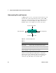
A VEE program consists of the objects in the work area and
the lines that connect them. The lines that connect VEE
objects are connected between object pins. Each object has
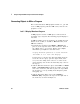
several pins, as shown in Figure 18. Figure 18 uses the
Formula object as an example. You can use any object.
.
Figure 18 Data and Sequence Pins
Connect the data input and output pins to carry data
between objects. By default, the pins execute from top to
bottom. The sequence pin connections are optional. If
connected, they will dictate an execution order.
Sequence Input Pin
Sequence Output Pin
Data Input Pin Data Output Pin
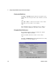
Table 4
Pin Type .Description
Data Input Pin The pin (or pins) on the left-hand side of an object.
Data Output Pin The pin (or pins) on the right-hand side of an object.
Sequence Input Pin The pin on the top of an object.
Sequence Output Pin The pin on the bottom of an object.