Agilent Acqiris Broadband High-Speed Digitizers Using 89600 Vector Signal Analyzer Software Application Note Vector signal analysis using Agilent Acqiris broadband digitizers.
Table of Contents 1 Overview 1.1 89600 VSA software 1.2 Required software revisions 2 Install 89600 VSA Software 3 Hardware Configuration 3.1 I/O between computer and digitizer 3.2 Anti-alias filters and alias exposure-free mode 4 Operation 4.1 Basic operation 4.2 Sampling modes: full rate and user rate 4.3 Differences from 89600 VSA operation 5 Time and Frequency Span Operating Region 5.1 The relationship of main time length, span, and sample rate 5.
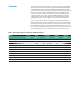
1 Overview This product note describes the characteristics, setup, and operation of a broadband vector signal analyzer (VSA) comprised of an Agilent Acqiris U1066A (DC440, DC438) or U1065A (DC282, DC252, DC222) high-speed digitizer and the 89600 vector signal analyzer software. By taking advantage of the layered architecture and extensive digital signal processing (DSP) routines of the 89600 VSA software, the digitizer becomes a new “front end” data acquisition subsystem for the VSA.
1.1 89600 VSA software The 89600 vector signal analyzer software is the heart of the broadband VSA. This software provides flexible tools for analyzing and demodulating even the most advanced digital modulations, including those not defined by an established standard. The VSA makes measurements on signals in the time and frequency domains using either the BB (baseband) or IF Zoom mode. In BB mode, the analysis frequency range is from 0 Hz to the stop frequency.
2 Install 89600 VSA Software The 89600 VSA software must be installed on a computer. Installation for standard operation Insert the Agilent Technologies 89600 Series Software CD-ROM in your standard PC and follow the instructions in the installation wizard. When the Installation Manager window opens, click Install 89600 Series Software. In the Hardware Support window, select Acqiris VSA Server. This will avoid installing unnecessary components on your computer.
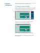
3 Hardware Configuration Connect the digitizer to the computer as shown in Figure 1a or 1b. There are two options for the connection, by remote computer or by embedded computer. 3.1 I/O between computer and digitizer Operation of the 89600 Series software on an embedded Compact PCI computer is similar to operation on a standard PC. The instructions for standard operation can be followed here as well using a LAN or USB accessible CD drive.
3.2 Anti-alias filters and alias exposure-free mode The broadband VSA can be configured to be essentially alias-free by using the full rate sampling mode and installing an external lowpass filter on the digitizer input. Use BNC-f to SMA-m and SMA-f to BNC-m adapters to connect the filter’s SMA connectors to the digitizer in case the digitizer has BNC connectors. Table 3.
4 Operation 4.1 Basic operation Operation of the broadband VSA is substantially the same as that of the 89600 VSA. See the following sections for some differences or special configurations. There is an online Tutorial and Getting Started Guide under the Help/Roadmap toolbar in the 89600 software. 4.
User rate mode The user rate setting allows you to directly control the digitizer’s sample rate. In this mode you select the digitizer sample rate to be used. The actual sample rate selected will be the highest rate that is less than or equal to the “user sample rate” setting. By controlling the digitizer’s sample rate you can directly influence the update rate of the VSA. This is because sample rate directly affects the number of points the digitizer must transfer to the PC.
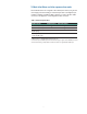
This table summarizes the difference in approach to alias protection between the various sample modes: Table 5. Varying approaches for alias protection Full rate Both in-band and out-of-band aliasing are prevented through use of the maximum sample rate and an appropriate lowpass filter. User rate You are responsible to avoid in-band aliasing through appropriate selection of sample rate based on center frequency and span.
5 Time and Frequency Span Operating Region The operating region curves for the broadband VSAs are different from those of standard VSAs because the Main Time Length may be limited for some sample rate, center frequency, and span combinations.
5.2 Operating region curves for Agilent Acqiris digitizers Several interrelated characteristics of both the Acqiris digitizers and the 89600 VSA software combine to form a region within which the VSA is constrained to operate. The 89600 VSA software characteristics that affect this operating region include maximum number of time points, the minimum number of time points (not user settable), a maximum acquisition record size (not user settable) and a maximum decimation factor (not user settable).
In addition to the time record length limits, there are limits to the allowable range of spans. These are represented as vertical lines on the operating region graphs (Figure 4). The upper span limit is set by the digitizer’s sample rate. For the highest sample rate supported by the digitizer this boundary may be further limited by the analog performance of the digitizer’s front-end.
Operating region: span constraints 1.E+01 1.E+00 1.E-02 1.E-03 1.E-04 Number of frequency points Time record length (sec) 1.E-01 409601 204801 102401 51201 25601 12801 6401 3201 1601 801 401 201 Operating region 1.E-05 1.E-06 1.E-07 Minimum 1.E-08 1.E+02 1.E+03 1.E+04 1.E+05 1.E+06 1.E+07 1.E+08 1.E+09 1.E+10 1.E+11 Span (Hz) Figure 4. The allowable range of spans, which may differ by model, further bound the operating region of the digitizer Operating region: with memory constraints 1.
In full rate sample mode with the use of appropriate lowpass filtering (Table 3) signal aliasing is completely avoided. In this case the “Operating Region” is renamed “Alias Exposure Free Zone” to indicate this special condition. NOTE: Does not apply to HF operation.
5.3 Recording limits for Acqiris digitizers The 89600 VSA software allows the acquisition of long records to be captured. Analysis is done as a post-processing operation. This feature is called Recording. Recordings can be much longer than time records in live measurements. Prior to taking a recording, live test measurements of Main Time length are usually made at the desired span.
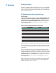
6 Out-of-Band Alias Exposure Zones As mentioned above, the user rate sampling modes increase the maximum Main Time length at the expense of possible aliasing of out-of-band signals into the frequency span of the measurement. The spectrum ranges subject to the alias conversion are called alias exposure zones. To determine if any out-of-band signals exist in the exposure zones, run the Alias Exposure Zone Checker macro. 6.
Trace C Trace A Figure 7. Alias Exposure Zone Checker results. The desired signal is at 150 MHz and an out-ofband signal is at –35 dBc and 642 MHz. The unwanted signal in the second alias zone is 5 dB above the –40 dBc threshold line. When no alias zones exist because the current sampling mode is alias free, no orange zone boxes will appear. In addition, the message No Alias Zones Detected! Restore Initial Settings? will appear (see Figure 8). Figure 8. Alias checker results when no zones are detected.
When the original center frequency/span is inadvertently tuned to an alias response of a signal whose frequency is not the center frequency, the checker will attempt to suggest the signal’s frequency. The checker results at the desired center frequency location (box formed by white solid and dashed lines) will show no signal, and a large signal will appear in one of the zones, as shown in Figure 9. Further, all zone boxes will be well above the orange threshold line. Figure 9.
Appendix A Downconverting RF and Microwave Signals into the Range of the Agilent Acqiris Digitizers External components with wide bandwidths can be used to downconvert signals into the range of the broadband VSAs. The 89600 VSA software can account for the mixing equation of the external downconverter.
Appendix B PC Requirements to Run 89600 Software The 89600 requires a PC connected via the PCI extender to the Acqiris digitizer or an embedded PC.
Operating region Model: Acqiris U1065A (DC222, DC252, DC282) Memory: 256 Mpts and 1024 Mpts 1.E+01 1.E+00 1.E-01 5 Msa/s 10 Msa/s 20 Msa/s 25 Msa/s 50 Msa/s 100 Msa/s 200 Msa/s / 250 Msa/s M 500 Msa/s 1 Gsa/s 2 Gsa/s a 4 Gsa/s 8 Gsa/s 1.E-04 1.E-05 409601 204801 102401 51201 25601 12801 Alias exposure free zone * 1.E-06 6401 3201 1601 801 401 1.E-07 1.E-08 1.E +02 1.E +03 1.E +04 201 Minimum Time Rec Len * One-channel operation only. ** Maximum span depends on model number – See Table 1.
For More Information For more product literature visit www.agilent.com/find/89600 Related literature list 89600 Series Vector Signal Analyzers Installation and VXI Service Guide Go to www.agilent.com/find/89600 then click on Technical Support > Manuals.
Agilent Email Updates www.agilent.com/find/emailupdates Get the latest information on the products and applications you select. Agilent Direct www.agilent.com/find/agilentdirect Quickly choose and use your test equipment solutions with confidence. Agilent Open www.agilent.com/find/open Agilent Open simplifies the process of connecting and programming test systems to help engineers design, validate and manufacture electronic products.