
User`s guide


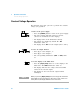
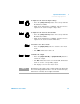
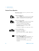
Table Of Contents
- Agilent U8030A Series Triple Output DC Power Supply
- Table of Contents
- List of Figures
- List of Tables
- Introduction
- Operation and Features
- Constant Voltage Operation
- Constant Current Operation
- 5 V Operation
- Track Mode Operation
- Output On/Off Operation
- Memory Operations
- Memory Output Operations
- Programming the Overvoltage Protection
- Programming the Overcurrent Protection
- Keylock Operation
- System-Related Operations
- Extending the Voltage and Current Range
- Characteristics and Specifications

Introduction 1
Your Power Supply in Brief
U8030A Series User’s Guide 31
Table 1 - 4 LCD display legends and descriptions
Legend Description
1 M1 Stores the current power supply operating state in
the power supply non-volatile memory.
When the power supply is in the calibration mode,
these states can be used to store the calibration
constants.
2 M2
3 M3
4 Δt
When the Δt annunciator is steady, the single
memory output operation is active.
When the Δt annunciator is blinking, the loop
memory output operation is active.
5 LOCK Front panel operation is disabled.
6 LIMIT
The voltage and current limit values are shown in
the display.
7 OFF All the power supply outputs are disabled.
8 88.88 V
Line 1: Voltage and current values display for
Output 1.
9 8.88 A
10 88.88 V
Line 2: Voltage and current values display for
Output 2.
11 8.88 A
12 OVP1
When the OVP1 annunciator is steady, the
overvoltage protection function for Output 1 is
enabled.
When the OVP1 annunciator is blinking, an
overvoltage condition has occurred. The power
supply output is disabled until the trip is cleared.
13 OCP1
When the OCP1 annunciator is steady, the
overcurrent protection function for Output 1 is
enabled.
When the OCP1 annunciator is blinking, an
overcurrent condition has occurred. The power
supply output is disabled until the trip is cleared.