
User`s guide
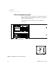
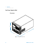
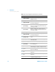
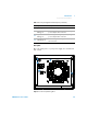
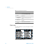
Table Of Contents
- Agilent U8030A Series Triple Output DC Power Supply
- Table of Contents
- List of Figures
- List of Tables
- Introduction
- Operation and Features
- Constant Voltage Operation
- Constant Current Operation
- 5 V Operation
- Track Mode Operation
- Output On/Off Operation
- Memory Operations
- Memory Output Operations
- Programming the Overvoltage Protection
- Programming the Overcurrent Protection
- Keylock Operation
- System-Related Operations
- Extending the Voltage and Current Range
- Characteristics and Specifications

Introduction 1
Preparing Your Power Supply
U8030A Series User’s Guide 21
2 Verify the power- line voltage setting.
The line voltage is set to the proper value for your
country when the power supply is shipped from the
factory. Change the voltage setting if it is not correct. The
settings are: 100, 115, or 230 V
AC.
3 Verify that the correct power- line fuse is installed.
The correct fuse for your country is installed when the
power supply is shipped from the factory. See the table
below to replace the fuse for your power supply.
Checking the instrument output
The following procedures check to ensure that the power
supply develops its rated outputs and properly responds to
operation from the front panel. For complete performance
and verification tests, refer to the U8030A Series Service
Guide.
From the front- panel VFD (vacuum- fluorescent display), you
can monitor actual values of output voltage and current
(meter mode) or voltage and current limit values (limit
mode).
Table 1 - 1 List of rated fuse for line voltages
Model Agilent part number Part description
U8031A/
U8032A
2110-1504
FUSE 1.0 A TIME-DELAY 0.0757 Ω
20 mm × 5.2 mm × 5.2 mm
NOTE
If an error is detected during the output checkout procedure, the Err
annunciator will turn on. For more information, refer to the “List of Error
Codes” on page 35.