Agilent U8030A Series Triple Output DC Power Supply User’s Guide Agilent Technologies
Notices © Agilent Technologies, Inc., 2011-2012 Warranty No part of this manual may be reproduced in any form or by any means (including electronic storage and retrieval or translation into a foreign language) without prior agreement and written consent from Agilent Technologies, Inc. as governed by United States and international copyright laws. The material contained in this document is provided “as is,” and is subject to change, without notice, in future editions.
Safety Symbols The following symbols on the instrument and in the documentation indicate precautions which must be taken to maintain safe operation of the instrument. Caution, risk of danger (refer to this manual for specific Warning or Caution information) In position of a bi-stable push control DC (Direct current or voltage) Terminal is at earth potential. Used for measurement and control circuits designed to be operated with one terminal at earth potential.
Safety Considerations Read the information below before using this instrument. The following general safety precautions must be observed during all phases of operation, service, and repair of this instrument. Failure to comply with these precautions or with specific warnings elsewhere in this manual violates safety standards for design, manufacture, and intended use of the instrument. Agilent Technologies assumes no liability for the customer’s failure to comply with these requirements.
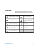
Environmental Conditions This instrument is designed for indoor use and in an area with low condensation. The table below shows the general environmental requirements for this instrument.
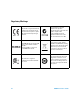
Regulatory Markings VI The CE mark is a registered trademark of the European Community. This CE mark shows that the product complies with all the relevant European Legal Directives. The C-tick mark is a registered trademark of the Spectrum Management Agency of Australia. This signifies compliance with the Australia EMC Framework regulations under the terms of the Radio Communication Act of 1992. ICES/NMB-001 indicates that this ISM device complies with the Canadian ICES-001.
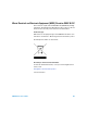
Waste Electrical and Electronic Equipment (WEEE) Directive 2002/96/EC This instrument complies with the WEEE Directive (2002/96/EC) marking requirement. This affixed product label indicates that you must not discard this electrical or electronic product in domestic household waste. Product Category: With reference to the equipment types in the WEEE directive Annex 1, this instrument is classified as a “Monitoring and Control Instrument” product. The affixed product label is as shown below.
Declaration of Conformity (DoC) The Declaration of Conformity (DoC) for this instrument is available on the Agilent website. You can search the DoC by its product model or description at the web address below. http://regulations.corporate.agilent.com/DoC/search.htm NOTE VIII If you are unable to search for the respective DoC, please contact your local Agilent representative.
Table of Contents 1 Introduction About This Manual 18 Documentation map 18 Safety notes 18 Preparing Your Power Supply 19 Checking the shipment 19 Connecting power to the instrument 20 Checking the instrument output 21 Rack-mounting the instrument 24 Enabling or disabling the backlight 25 Your Power Supply in Brief 26 Dimensions 26 Overview 27 Display screen 30 Output connections 33 Operating Your Power Supply Cooling 34 Bench operation 34 Cleaning 34 List of Error Codes 35 System errors 35 Power channel e
Circuit fault condition Track Mode Operation 43 44 Output On/Off Operation 45 Turn on or off all outputs 45 Turn on or off individual outputs 46 Memory Operations 47 Storing an operating state 47 Recalling an operating state 48 Memory Output Operations 49 Enable the memory output single operation 49 Enable the memory output loop operation 50 Program the memory output time interval 51 Programming the Overvoltage Protection 52 Set the OVP trip level and enable the OVP 52 Disable the OVP 53 Clear the overv
3 Characteristics and Specifications Electrical Specifications 66 Physical Characteristics 67 Supplemental Characteristics Protection Features 68 69 AC Power Input Specifications Environmental Specifications Connection Specifications U8030A Series User’s Guide 69 70 70 XI
XII U8030A Series User’s Guide
List of Figures Figure 1-1 Figure 1-2 Figure 1-3 Figure 1-4 Figure 1-5 Figure 1-6 Figure 2-1 Figure 2-2 U8030A Series User’s Guide Rack-mount adapter kit 24 U8030A Series rack-mount dimensions 24 U8030A Series dimensions 26 The front panel at a glance 27 The rear panel at a glance 29 The LCD display at a glance 30 Connecting units in series 62 Connecting units in parallel 63 XIII
XIV U8030A Series User’s Guide
List of Tables Table 1-1 Table 1-2 Table 1-3 Table 1-4 Table 1-5 Table 1-6 Table 3-1 Table 3-2 Table 3-3 Table 3-4 Table 3-5 Table 3-6 Table 3-7 U8030A Series User’s Guide List of rated fuse for line voltages 21 Front panel legends and descriptions 27 Rear panel legends and descriptions 30 LCD display legends and descriptions 31 List of system error codes 35 List of power channel error codes 35 Electrical specifications 66 Physical characteristics 67 Supplemental characteristics 68 Protection features 69
XVI U8030A Series User’s Guide
U8030A Series Triple Output DC Power Supply User’s Guide 1 Introduction About This Manual 18 Documentation map 18 Safety notes 18 Preparing Your Power Supply 19 Checking the shipment 19 Connecting power to the instrument 20 Checking the instrument output 21 Rack-mounting the instrument 24 Enabling or disabling the backlight 25 Your Power Supply in Brief 26 Dimensions 26 Overview 27 Display screen 30 Output connections 33 Operating Your Power Supply 34 Cooling 34 Bench operation 34 Cleaning 34 List of Error
1 Introduction About This Manual About This Manual The descriptions and instructions in this manual apply to the Agilent U8031A and U8032A triple output DC power supplies (hereafter referred to as the power supply). The model U8032A appears in all illustrations. Documentation map The following manuals are available for your power supply. For the latest version, please visit our website at: http://www.agilent.com/find/U8030. Check the manual revision on the first page of each manual. • User’s Guide.
Introduction Preparing Your Power Supply 1 Preparing Your Power Supply Checking the shipment When you receive your power supply, check the shipment according to the following procedure. 1 Inspect the shipping container for damage. Signs of damage may include a dented or torn shipping container or cushioning material that indicates signs of unusual stress or compacting. Save the packaging material in case the power supply needs to be returned.
1 Introduction Preparing Your Power Supply Connecting power to the instrument Connect the power cord to the AC power connector (see page 29 for the AC power connector location). Before connecting the mains plug, ensure that the line voltage selection is appropriate for your location (100 V, 115 V, or 230 V). The mains plug should only be inserted into a socket outlet that provides protective earth contact. Push the power switch to turn on the instrument.
Introduction Preparing Your Power Supply 1 2 Verify the power- line voltage setting. The line voltage is set to the proper value for your country when the power supply is shipped from the factory. Change the voltage setting if it is not correct. The settings are: 100, 115, or 230 VAC. 3 Verify that the correct power- line fuse is installed. The correct fuse for your country is installed when the power supply is shipped from the factory. See the table below to replace the fuse for your power supply.
1 Introduction Preparing Your Power Supply Voltage output check The following steps verify basic voltage functions with no load. 1 Turn on the power supply. The power supply starts up for the first time in the power- on (reset) state — all the outputs are disabled (the OFF annunciator is turned on). 2 Enable the outputs. Press the [All On/Off] button once. Notice that the display is in the meter mode.
Introduction Preparing Your Power Supply 1 3 Turn on the power supply. Ensure that all the outputs are disabled (the OFF annunciator is turned on). 4 Enable the output for Output 1. Press the [Output 1 On/Off] button (the OFF annunciator for OUT1 turns off). Notice that the display is in the meter mode. 5 Adjust the voltage limit value to 1.00 V. Press the [Display Limit] button to set the display to the limit mode (the LIMIT annunciator turns on). Adjust the voltage limit to 1.
1 Introduction Preparing Your Power Supply Rack-mounting the instrument You can mount the power supply in a standard 19- inch rack cabinet. Instructions and mounting hardware are included with the rack- mounting kit. To rack- mount a single instrument, order adapter kit 5063- 9245.
Introduction Preparing Your Power Supply 1 Enabling or disabling the backlight You can enable or disable the LCD backlight through the front panel. Press the [Back Light] button to disable the LCD backlight. If viewing the display becomes difficult in low- light conditions, press the [Back Light] button again to enable the LCD backlight. NOTE U8030A Series User’s Guide The LCD backlight is enabled by default upon power-on.
1 Introduction Your Power Supply in Brief Your Power Supply in Brief Dimensions 179.0 mm 379.0 mm 212.
Introduction Your Power Supply in Brief 1 Overview Front panel The front panel parts of your power supply are described in this section. Figure 1-4 The front panel at a glance Table 1-2 Front panel legends and descriptions U8030A Series User’s Guide Legend Description 1 LCD display Displays the instrument settings and readings. 2 [Memory] Stores the current operating state or recalls a previously stored operating state from the available memory locations (M1, M2, or M3).
1 Introduction Your Power Supply in Brief Table 1-2 Front panel legends and descriptions (continued) 28 Legend Description 3 [Memory Output] Recalls all stored operating in sequence once (single) or in a loop. 4 [Δ t] Adjusts the memory output time interval. 5 [Output 1 On/Off] Enables or disables the power supply output from the Output 1 binding posts. 6 [Over Voltage] Enables or disables the overvoltage protection function, sets the trip voltage level, and clears the overvoltage condition.
Introduction Your Power Supply in Brief 1 Table 1-2 Front panel legends and descriptions (continued) Legend Description 19 [POWER] Turns the power supply on or off. 20 Output 1 binding posts Positive, negative, and ground (shared) binding posts for Output 1 wire connections. 21 Output 2 binding posts Positive, negative, and ground (shared) binding posts for Output 2 wire connections. 22 5 V binding posts Positive and negative binding posts for 5 V output wire connections.
1 Introduction Your Power Supply in Brief Table 1-3 Rear panel legends and descriptions Legend Description 1 AC line fuse To maintain protection, replace this fuse only with a fuse of the specified type and rating. 2 AC inlet Connects the AC power line. Plug the power cord firmly in here. 3 Line voltage and fuse rating selector Set the line voltage and line fuse rating to the proper values that are appropriate for your location.
Introduction Your Power Supply in Brief 1 Table 1-4 LCD display legends and descriptions Legend Description 1 M1 2 M2 Stores the current power supply operating state in the power supply non-volatile memory. 3 M3 When the Δt annunciator is steady, the single memory output operation is active. 4 Δt 5 LOCK Front panel operation is disabled. 6 LIMIT The voltage and current limit values are shown in the display. 7 OFF All the power supply outputs are disabled. 8 88.88 V 9 8.
1 Introduction Your Power Supply in Brief Table 1-4 LCD display legends and descriptions Legend 14 OVP2 Description When the OVP2 annunciator is steady, the overvoltage protection function for Output 2 is enabled. When the OVP2 annunciator is blinking, an overvoltage condition has occurred. The power supply output is disabled until the trip is cleared. When the OCP2 annunciator is steady, the overcurrent protection function for Output 2 is enabled.
Introduction Your Power Supply in Brief 1 Output connections WA R N I N G Before attempting to connect wires to the front output terminals, make sure to disable the power supply output first to avoid damage to the circuits being connected. Voltage drops The load wires must be large enough to avoid excessive voltage drops due to the impedance of the wires.
1 Introduction Operating Your Power Supply Operating Your Power Supply Cooling The power supply can operate at rated specifications within the temperature range of 0 °C to 40 °C. Power supply loading is derated from 40 °C to 55 °C. A fan cools the power supply by drawing air through the sides and exhausting it out the back. Using an Agilent rack- mount will not impede the flow of air.
Introduction List of Error Codes 1 List of Error Codes The following errors indicate failures that may occur while operating the power supply.
1 Introduction List of Error Codes Table 1-6 List of power channel error codes (continued) 36 Error code Description 113 Failed to calibrate OCP 119 Analog board unknown error 120 Over temperature 130 Failed EEPROM test 131 Failed voltage +15 V 132 Failed voltage +5 V 133 Failed voltage +2.
U8030A Series Triple Output DC Power Supply User’s Guide 2 Operation and Features Constant Voltage Operation 38 Constant Current Operation 40 5 V Operation 42 Track Mode Operation 44 Output On/Off Operation 45 Memory Operations 47 Memory Output Operations 49 Programming the Overvoltage Protection 52 Programming the Overcurrent Protection 55 Keylock Operation 58 System-Related Operations 59 Extending the Voltage and Current Range 61 This chapter shows you the operations and features for the U8030A Series t
2 Operation and Features Constant Voltage Operation Constant Voltage Operation The following steps show you how to perform the constant voltage (CV) operation. 1 Turn on the power supply. • Press the [POWER] button to turn on the power supply. • The power supply will then perform a self- test (self- test is not indicated at the display). • The display turns on all annunciators briefly. • The outputs are disabled by default. The OFF annunciator turns on.
Operation and Features Constant Voltage Operation 2 4 Adjust for the desired output voltage. • Press the [Voltage/Current] button if necessary until the V annunciator blinks. • While the V annunciator is blinking, turn the knob to adjust for the desired output voltage value. 5 Adjust for the desired current limit. • Press the [Voltage/Current] button if necessary until the A annunciator blinks. • While the A annunciator is blinking, turn the knob to adjust for the desired current limit value.
2 Operation and Features Constant Current Operation Constant Current Operation The following steps show you how to perform the constant current (CC) operation. 1 Short the binding posts. • Press the [POWER] button to turn off the power supply. • Connect a short circuit between the positive (+) and negative (—) binding posts of your desired output. 2 Turn on the power supply. • Press the [POWER] button to turn on the power supply.
Operation and Features Constant Current Operation NOTE 2 When you press the [Display Limit] button, the voltage and current limit values will be shown on the display for about five seconds. If there is no activity detected, the display will return to the meter mode. 5 Adjust for the desired voltage limit. • Press the [Voltage/Current] button if necessary until the V annunciator blinks. • While the V annunciator is blinking, turn the knob to adjust for the desired output voltage value.
2 Operation and Features 5 V Operation 5 V Operation The following steps show you how to output a constant 5 V from the 5 V output channel. 1 Turn on the power supply. • Press the [POWER] button to turn on the power supply. • The power supply will then perform a self- test (self- test is not indicated at the display). • The display turns on all annunciators briefly. • The outputs are disabled by default. The OFF annunciator turns on. • The display shows OFF for both outputs (line 1 and 2).
Operation and Features 5 V Operation 2 Circuit fault condition When an internal circuit fault is detected, the 5 V output will be disabled automatically. • The 5 V annunciator blinks. • The circuit fault condition might be cleared by cycling the unit power. • If the fault condition persists, stop using the unit and send it to an authorized service center for repair.
2 Operation and Features Track Mode Operation Track Mode Operation When the track mode is enabled, the voltage settings of Output 1 and Output 2 will mirror each other. The following steps show you how to track the voltage of the selected output. 1 Select an output channel. • Press [1] to select Output 1, or • Press [2] to select Output 2. • The corresponding annunciator (OUT1 or OUT2) turns on. 2 Set the desired voltage setting for the selected output channel.
Operation and Features Output On/Off Operation 2 Output On/Off Operation The following steps show you how to turn on all outputs at the same time or to turn on each output individually. Turn on or off all outputs When the power supply is turned on, all outputs (Output 1, Output 2, and the 5 V output) are disabled by default. 1 Enable all outputs at the same time. • Press the [All On/Off] button to enable all the outputs in a single button press. • The OFF annunciator turns off.
2 Operation and Features Output On/Off Operation Turn on or off individual outputs Each output can be individually enabled or disabled by pressing its corresponding On/Off button. 1 Enable or disable Output 1. • Press the [Output 1 On/Off] button to enable Output 1. • The display shows voltage and current values for Output 1 on line 1. • The display Output 2 on line 2 remains unchanged. • Press the [Output 1 On/Off] button again to disable Output 1. 2 Enable or disable Output 2.
Operation and Features Memory Operations 2 Memory Operations Up to three operating states can be stored in the non- volatile storage locations. The storage feature remembers the voltage and current limit value settings; OVP and OCP on or off states; and OVP and OCP trip levels. The following steps show you how to store and recall an operating state. Storing an operating state 1 Store the power supply current operating state. • Press the [Memory] button. • The M1 annunciator will blink.
2 Operation and Features Memory Operations Recalling an operating state 1 Recall a previously stored operating state. • Press and hold the [Memory] button until the M1 annunciator stops blinking. • The M1 annunciator turns on. • The display shows the settings stored in the M1 memory location. 2 Turn the knob to show the settings saved in M1, M2, and M3 memory locations. • The M1, M2, and M3 annunciators will turn on in a round- robin manner.
Operation and Features Memory Output Operations 2 Memory Output Operations The Memory Output feature allows operating states from the M1, M2, and M3 memory locations to be recalled automatically in sequential order. Three time intervals are programmable: • Δt1 — time delay between recalling M1 and recalling M2. • Δt2 — time delay between recalling M2 and recalling M3. • Δt3 — time delay between recalling M3 and recalling M1.
2 Operation and Features Memory Output Operations • The Δt annunciator turns off, and all the M1, M2, and M3 annunciators turn off. Enable the memory output loop operation 1 Enable the memory output loop operation. • Press and hold the [Memory Output] button until the Δt annunciator starts to blink. (The Δt annunciator turns on first before it starts to blink.) • All the M1, M2, and M3 annunciators turn on. • The operating state from M1 memory location is recalled immediately. • The M1 annunciator blinks.
Operation and Features Memory Output Operations 2 Program the memory output time interval 1 Edit the memory output time interval. • Press the [Δt] button. • The Δt annunciator turns on. • By default, the M1 annunciator turns on indicating Δt1 is being selected for adjustment. • To select Δt2 or Δt3, press the [Memory] button until the corresponding M2 or M3 annunciator turns on. • The display shows the time interval in seconds, with the integral part on line 1 and the fractional part on line 2.
2 Operation and Features Programming the Overvoltage Protection Programming the Overvoltage Protection Overvoltage protection guards the load against output voltages reaching values greater than the programmed protection level. The following steps shows you how to enable and disable the overvoltage protection (OVP), how to set the OVP trip level, and how to clear the overvoltage condition. Set the OVP trip level and enable the OVP 1 Select an output channel.
Operation and Features Programming the Overvoltage Protection 2 4 Enable the OVP. • Press the [Over Voltage] button again to end the adjustment and enable the OVP. • The display will show dOnE. • The corresponding OVP annunciator (OVP1 or OVP2) turns on. NOTE To cancel this operation, allow the unit to idle for five seconds. Disable the OVP 1 Select an output channel with OVP enabled. • Press [1] to select Output 1, or • Press [2] to select Output 2.
2 Operation and Features Programming the Overvoltage Protection • If the OVP trip occurs on Output 2, the display shows triP on line 2 and the OVP2 annunciator blinks. 1 Select the output channel with the OVP trip. • Press [1] to select Output 1, or • Press [2] to select Output 2. • The corresponding annunciator (OUT1 or OUT2) turns on. 2 Clear the OVP trip. • Press the [Over Voltage] button again to clear the OVP trip.
Operation and Features Programming the Overcurrent Protection 2 Programming the Overcurrent Protection Overcurrent protection guards the load against output currents reaching values greater than the programmed protection level. The following steps shows you how to enable and disable the overcurrent protection (OCP), how to set the OCP trip level, and how to clear the overcurrent condition. Set the OCP trip level and enable the OCP 1 Select an output channel.
2 Operation and Features Programming the Overcurrent Protection 4 Enable the OCP. • Press the [Over Current] button again to end the adjustment and enable the OCP. • The display will show dOnE. • The corresponding OCP annunciator (OCP1 or OCP2) turns on. NOTE To cancel this operation, allow the unit to idle for five seconds. Disable the OCP 1 Select an output channel with OCP enabled. • Press [1] to select Output 1, or • Press [2] to select Output 2.
Operation and Features Programming the Overcurrent Protection 2 • If the OCP trip occurs on Output 2, the display shows triP on line 2 and the OCP2 annunciator blinks. 1 Select the output channel with the OCP trip. • Press [1] to select Output 1, or • Press [2] to select Output 2. • The corresponding annunciator (OUT1 or OUT2) turns on. 2 Clear the OCP trip. • Press the [Over Current] button again to clear the OCP trip.
2 Operation and Features Keylock Operation Keylock Operation This operation provides a locking function for the knob and all the buttons on the front panel of the power supply, which allows you to secure your desired settings. The keylock is disabled by default upon power- up. 1 Enable the keylock. • Press the [Lock/Unlock] button. • The LOCK annunciator turns on. • When the keylock function is enabled, the knob and all the buttons are disabled except the [Lock/Unlock] button. 2 Disable the keylock.
Operation and Features System-Related Operations 2 System-Related Operations Reset to the factory defaults To reset to factory defaults, press and hold the [All On/Off] button when powering on the unit until the display shows dOnE. • The OVP and OCP are disabled, and their trip levels are set to maximum (i.e., 10% above the CV and CC rated values). • All memory storage locations are cleared. • The voltage limit value is set to 0, while the current limit value is set to the maximum rated value.
2 Operation and Features System-Related Operations Display the firmware and board versions To display the firmware and board versions, press and hold the [Over Voltage] and [Display Limit] buttons simultaneously when powering on the unit. • The display shows the front panel firmware version on line 1 for one second. • After that, the display shows: • the firmware and board versions of analog board 1 on line 1, and • the firmware and board versions of analog board 2 on line 2 for one second.
Operation and Features Extending the Voltage and Current Range 2 Extending the Voltage and Current Range CAUTION • Never exceed the floating voltage rating of any of the supplies. • Never subject any of the power supplies to negative voltages. Two or more power supplies can be connected in series or parallel to extend the range of voltage and current. This may serve as a lower cost alternative to a power supply with higher power rating.
2 Operation and Features Extending the Voltage and Current Range Figure 2-1 Connecting units in series Parallel connection Two or more power supplies which are capable of constant voltage or constant current automatic cross- over operation can be connected in parallel to obtain a total output current greater than one power supply. Total output current is the sum of output current across all power supplies. The output settings from each power supply can be made separately.
Operation and Features Extending the Voltage and Current Range 2 Figure 2-2 Connecting units in parallel U8030A Series User’s Guide 63
2 Operation and Features Extending the Voltage and Current Range THIS PAGE HAS BEEN INTENTIONALLY LEFT BLANK.
U8030A Series Triple Output DC Power Supply User’s Guide 3 Characteristics and Specifications Electrical Specifications 66 Physical Characteristics 67 Supplemental Characteristics 68 Protection Features 69 AC Power Input Specifications 69 Environmental Specifications 70 Connection Specifications 70 This chapter lists the characteristics and specifications of the U8031A and U8032A triple output DC power supplies.
3 Characteristics and Specifications Electrical Specifications Electrical Specifications NOTE The specifications stated are based on a 1 hour warm-up period.
Characteristics and Specifications Physical Characteristics 3 Table 3-1 Electrical specifications (continued) Parameter U8031A U8032A Stability (output drift) Following a 30-minute warm-up, with the output in the ON state according to the operating mode (CC with load or CV), and with a change in the output over 8 hours under constant load, line, and ambient temperature. • Voltage: <0.02% • Current: <0.1% Programming accuracy (23 °C ± 5 °C) • CV: ≤0.25% + 15 mV • CC: ≤0.
3 Characteristics and Specifications Supplemental Characteristics Supplemental Characteristics Table 3-3 Supplemental characteristics Parameter U8031A/U8032A Temperature coefficient (for 12 months) ±(% of output + offset) • Output • CV: (0.01% + 1 mV) / °C • CC: (0.01% + 1 mA) / °C • OVP, OCP • CV: <0.05% / °C • CC: <0.05% / °C Output voltage overshoot During turn-on or turn-off of AC power, if output control is set less than 1 V.
Characteristics and Specifications Protection Features 3 Protection Features Table 3-4 Protection features Parameter U8031A Overvoltage protection accuracy ± (% of output + offset) <0.5% +0.5V Overvoltage protection programmable range 0.1 V to 33.0 V Overvoltage protection response time <10 ms Overcurrent protection accuracy <0.5% + 0.5 A U8032A 0.1 V to 66.0 V ± (% of output + offset) Overcurrent protection programmable range 0.1 A to 6.6 A Overcurrent protection response time <10 ms 0.
3 Characteristics and Specifications Environmental Specifications Environmental Specifications Table 3-6 Environmental specifications Parameter U8031A/U8032A Operating temperature 0 °C to 40 °C Storage temperature –40 °C to 70 °C Humidity 15% RH (relative humidity) to 85% RH at 40 °C (non-condensing) Altitude Up to 2000 meters Fan acoustic noise • No load: follow Agilent Class CO, 45 dB sound pressure and 50 dB sound power • Full load: follow Agilent Class GP, 55 dB sound pressure and 60 dB sou
www.agilent.