
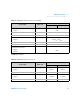
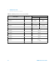
Technical data
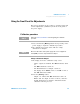

1 Calibration Procedures
Using the Front Panel for Adjustments
32 U8030A Series Service Guide
• Output 2 is enabled. The OFF annunciator turns off.
• Ensure that the output is in the CV mode, otherwise
the CC annunciator for Output 2 will blink and the
calibration will not proceed.
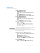
3 Voltage calibration low point:
• The M1 annunciator turns on.
• Use the knob to enter the reading obtained from the
DVM.
• Press the [Memory] button to save the value.
• The calibration proceeds to the next calibration point.
4 Voltage calibration high point:
• The M2 annunciator turns on.
• Use the knob to enter the reading obtained from the
DVM.
• Press the [Memory] button to save the value.
5 The voltage calibration for Output 2 is completed.
• Output 2 is disabled.
• The display shows DONE for a brief period of time.
• The calibration procedure proceeds to the current
calibration for Output 2.
Current calibration for Output 2
1 The display shows the calibration setup screen.
• All the outputs are disabled. The OFF annunciator turns
on.
• The OUT2 annunciator turns on.
• The CC annunciator for Output 2 turns on.
• The display shows SET UP on line 1 and CAL on line 2.
The CAL annunciator blinks.
NOTE
Connect an appropriate 0.01 Ω shunt resistor across the output terminals
of Output 2, and connect a DVM across the shunt resistor.