
Technical data
1 Calibration Procedures
Performance Verification Tests
16 U8030A Series Service Guide
11 Disconnect the oscilloscope, and connect an RMS
voltmeter in its place. Do not disconnect the 50 Ω
termination. Divide the reading of the RMS voltmeter by
10. The result should not exceed the RMS limits of
• 1 mV
RMS
for U8031A and U8032A, and
• 2 mV
RMS
for Output 3.
Load transient response time
This test measures the time for the output voltage to recover
to within 15 mV of the nominal output voltage following a
load change from full load to half load or vice versa.
Procedure:
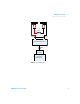
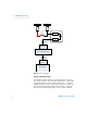
1 Power off the power supply, and connect the output to be
tested as shown in Figure 1- 1 with an oscilloscope.
Operate the electronic load in the CC mode.
2 Power on the power supply.
3 When the display is in the limit mode, program the
output voltage to full rated value (i.e., 30 V for U8031A
and 60 V for U8032A) and the output current to the
maximum programmable value.
4 Enable the output.
5 Set the electronic load to the transient operation mode
between one half of the output's full rated value and the
output's full rated value at a 1 kHz rate with 50% duty
cycle.
6 Set the oscilloscope coupling, internal sync, and lock on
to either the positive or negative load transient.
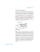
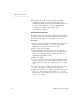
7 Adjust the oscilloscope to display transients as shown in
Figure 1- 6. Note that the pulse width (t
2
– t
1
) of the
transients at 15 mV from the base line is no more than
50 μs for the output.