
Technical data
Calibration Procedures 1
Performance Verification Tests
U8030A Series Service Guide 15
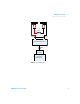
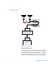
6 Configure the differential amplifier as follows.
• Enable the AC mode (positive and negative) to remove
the DC component
• Enable the differential mode
• Set the gain to ×10
• Set the attenuation to 1
• Set the low- pass filter to 20 MHz bandwidth limit to
filter out input signals that contain higher frequencies
• Enable the zero precision voltage generator
• Set the input impedance to 50 Ω
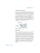
7 Configure the scope as follows.
• Set the time range to 50 ms (20 Hz)
• Acquire every single sample at the maximum sampling
rate and retain only the minimum and maximum values
in a “sampling region” (50 ms time range)
• Enable the 20 MHz cut- off frequency for better high
frequency cut- off
• Enable AC coupling
• Enable auto- triggering
8 Allow the scope run for a few seconds to generate enough
measurement points.
9 Obtain the maximum peak- to- peak voltage measurement
as indicated in the scope. Divide this value by 10 to get
the CV peak- to- peak noise measurement. The result
should not exceed
• 10 mV
pp
for U8031A and U8032A, and
• 50 mV
pp
for Output 3.
10 Configure the RMS voltmeter as follows.
• Set the high- pass filter to 10 Hz
• Enable AC coupling