
Technical data


Returning and Replacing a U4154A Module or its cables 6
U4154A Logic Analyzer Service Guide 87
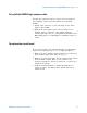
To install the U4201A logic analyzer cable
Perform the following steps to connect the new/replaced
logic analyzer cable to the front panel of the U4154A
module.
1 Attach cable connector to the pod input on the front
panel of the module.
2 Tighten the two thumb screws on both sides of the
U4201A cable to retain the cable tightly inside the
relevant pod input. Do not over tighten the thumb screws.
Hand tightening is recommended or maximum torque of
3in- lb.
I
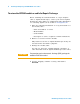
To replace the circuit board
If the circuit board of the U4154A module is found faulty,
perform the following steps to get it repaired/replaced.
1 Remove the logic analyzer cables using the “To remove the
logic analyzer cable” procedure on page 86.
2 Remove the U4154A module with the faulty circuit board
from the AXIe chassis. Refer to the U4154A Logic
Analyzer Installation Guide to learn how to remove the
module from chassis.
3 Send the U4154A module to Agilent Technologies to
repair or replace the faulty circuit board with a new
circuit board.