
Technical data

60 U4154A Logic Analyzer Service Guide
3 Testing U4154A Performance
Tes t P ods 3
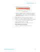
1 Disconnect the E5382A Flying Lead Probe Set from Pod 2
and connect it to Pod 3 of the logic analyzer. (The clock
input on Pod 1 is used when testing Pod 3.)
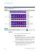
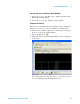
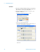
2 In the Buses/Signals setup dialog, set the Pod 1 clock
threshold to Differential:
a Drag the scroll bar all the way to the left.
b Select the Clock Thresholds button.
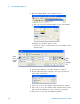
c In the Threshold Settings for Clock Channels dialog, set
the Pod 1 clock threshold to Differential.
Click Done.