
Technical data

58 U4154A Logic Analyzer Service Guide
3 Testing U4154A Performance
Test the complement of the bits
Now test the logic analyzer using inverted levels (in other
words, complement data).
1 On the pulse generator, in the PULSE setup for CHANNEL
2, select inverted levels:
• On the 81134A pulse generator, select Levels: Inverted.
• On the 8133A pulse generator, select COMP (LED on).
2 Verify the DC offset and adjust it if necessary. See
page 38.
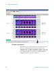
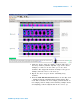
3 Adjust the sampling positions (run Eye Scan). See
page 48.
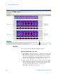
4 Determine pass or fail (1 of 2 tests). See page 54.
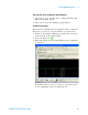
5 Switch to the Listing window by selecting the Listing tab
at the bottom of the main logic analyzer window.
6 Select the Run Repetitive icon .
7 Determine pass or fail (2 of 2 tests). See page 57.
Tes t P od 2
1 Disconnect the E5382A Flying Lead Probe Set from the
pulse generator outputs.
2 Connect the probe set from Pod 2 of logic analyzer to the
pulse generator outputs. (The clock input on Pod 1
remains the clock input when testing Pod 2.)
3 On the pulse generator, in the PULSE setup for CHANNEL
2, return the outputs to normal (non- inverted or
non- complement) levels.
4 Verify the DC offset and adjust it if necessary. See
page 38.
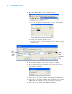
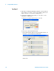
5 In the Overview window, select Setup→Bus/Signal... from
the module’s drop- down menu.
6 Scroll to the right and unassign all Pod 1 bits.
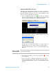
7 Set the Pod 2 threshold to 600 mV (just as you did for
Pod 1 on page 43).