
Technical data

Testing U4154A Performance 3
U4154A Logic Analyzer Service Guide 45
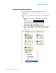
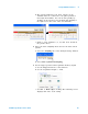
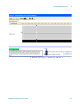
h The activity indicators now show activity on the
channels that are connected to the pulse generator.
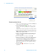
Un- assign all channels. You can do this quickly by
clicking on the left- most check mark and dragging to
the right across all of the other check marks.
i Click to select channels 2, 6, 10, and 14 as shown in
the picture above.
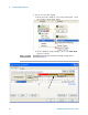
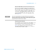
4 Select the State sampling mode and set the State Clock
options:
a Select the Sampling tab of the Analyzer Setup window.
b Select State - Synchronous Sampling.
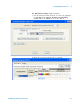
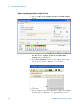
5 Set the trigger position and acquisition memory depth:
a Set the Trigger Position to 100% Poststore.
b Set the Acquisition Depth to 128K.
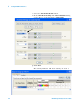
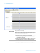
c Set Clk1 to Both edges clocking. The following screen
displays this state clock setting.