
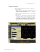
Technical data
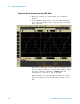

Testing U4154A Performance 3
U4154A Logic Analyzer Service Guide 37
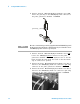
Connect the Pulse Generator Output to the Oscilloscope
1 Attach Male BNC to Female SMA adapters to Channels 1
and 2 on the oscilloscope.
2 Attach one end of an SMA cable to the Male BNC to
Female SMA adapter on Channel 1 of the oscilloscope.
3 Attach the other end of the SMA cable to the SMA/Flying
Lead connector at the Channel 2 OUTPUT of the pulse
generator.
4 Attach one end of the other SMA cable to the Male BNC
to Female SMA adapter on Channel 2 of the oscilloscope.
5 Attach the other end of the SMA cable to the SMA/Flying
Lead connector at the Channel 2 OUTPUT
of the pulse
generator.