
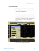
Technical data

36 U4154A Logic Analyzer Service Guide
3 Testing U4154A Performance
6 Connect the Pod 1 E5382A Flying Lead Probe Set’s CLK
lead to the pin strip of the SMA/Flying Lead connector at
the pulse generator’s Channel 1 OUTPUT.
7 Connect the Pod 1 E5382A Flying Lead Probe Set’s CLK
lead to the SMA/Flying Lead connector at the pulse
generator’s Channel 1 OUTPUT
. Again, be sure to use the
black ground clip and orient the leads so that the black
clip is connected to ground.
8 Connect the Pod 1 E5382A Flying Lead Probe Set’s bits 2
and 10 to the SMA/Flying Lead test connector’s pin strip
connector at the pulse generator’s Channel 2 OUTPUT
.
9 Connect the Pod 1 E5382A Flying Lead Probe Set’s bits 6
and 14 to the SMA/Flying Lead test connector’s pin strip
connector at the pulse generator’s Channel 2 OUTPUT.
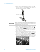
ground clip
NOTE
Be sure to use the black ground clip (supplied with the E5382A Flying Lead
Probe Set) and orient the leads so that the black clip is connected to one of
the SMA/Flying Lead connector’s ground pins!