
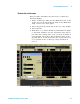
Technical data

Testing U4154A Performance 3
U4154A Logic Analyzer Service Guide 35
Connect the Test Equipment
Connect the U4154A Logic Analyzer Pod to the Pulse Generator
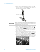
1 Connect Transition Time Converters (if required - see
page 25) to each of the four outputs of the pulse
generator: Channel 1 OUTPUT, Channel 1 OUTPUT
,
Channel 2 OUTPUT, Channel 2 OUTPUT
.
2 Connect the two SMA/Flying Lead test connectors (see
“Assemble the SMA/Flying Lead Test Connectors" on
page 26) with 50 ohm terminators to the Transition Time
Converters at the pulse generator Channel 1 OUTPUT and
Channel 1 OUTPUT
. (If Transition Time Converters are
not required, connect the SMA/Flying Lead test
connectors directly to the pulse generator outputs.)
3 Connect the two SMA/Flying Lead test connectors without
50 ohm terminators to the Transition Time Converters at
the pulse generator Channel 2 OUTPUT and Channel 2
OUTPUT
. (If Transition Time Converters are not required,
connect the SMA/Flying Lead test connectors directly to
the pulse generator outputs.)
4 Connect one E5382A Flying Lead Probe Set to Pod 2 of
the U4154A logic analyzer. This probe set is used later to
test data on pods 2 to 8.
5 Connect the other E5382A Flying Lead Probe Set to Pod 1
of the U4154A logic analyzer. This probe set is used for
the clock input.