
Technical data

32 U4154A Logic Analyzer Service Guide
3 Testing U4154A Performance
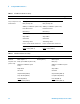
Table 5 81134A Pulse Generator Setup
Main Channel 2 Channel 1 Trigger
Mode: Pulse/Pattern Mode: Square ÷ 1Mode: Square ÷ 1 Disable
Freq: set in previous step. Timing Timing
Clock Internal Delay Ctrl Input Off Delay Ctrl Input Off
Width: (not available in square mode) Width: (not available in square mode)
Pulse Perf: Normal Pulse Perf: Normal
Deskew: 0ps Deskew: 0ps
Levels: Normal, Custom Levels: Normal, Custom
Ampl: 0.45 V Ampl: 0.45 V
Offset: 0.6 V Offset: 0.6 V
Term Voltage: 0 mV Term Voltage: 0 mV
Limit to current Levels: unselected Limit to current Levels: unselected
Output: Enable (LED on) Output: Enable (LED on)
Output
: Enable (LED on) Output: Enable (LED on)
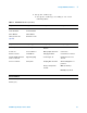
Table 6 8133A Pulse Generator Setup
Timebase Pulse Channel 2 Trigger Pulse Channel 1
Mode: Int Mode: Square ÷ 1 Disable (LED on) Mode: Square
Freq: was set in
previous step.
Delay: (not available in pulse mode) Delay: 0 ps
Width: (not available in square
mode)
Width: (not available in square
mode)
Ampl: 0.45 V Ampl: 0.45 V
Offs: 0.6 V Offs: 0.6 V
Output: Enable (LED off) Output: Enable (LED off)
Comp: Normal (LED off) Comp: Normal (LED off)
Limit: Off (LED off) Limit: Off (LED off)
Output
: Enable (LED off) Output: Enable (LED off)