Agilent U4154A Logic Analyzer Service Guide Agilent Technologies
Notices © Agilent Technologies, Inc. 2013 Manual Part Number No part of this manual may be reproduced in any form or by any means (including electronic storage and retrieval or translation into a foreign language) without prior agreement and written consent from Agilent Technologies, Inc. as governed by United States and international copyright laws. U4154-97005 Trademark Acknowledgements Windows and MS Windows are U.S. registered trademarks of Microsoft Corporation. Windows XP is a U.S.
Additional Safety Notices This apparatus has been designed and tested in accordance with IEC Publication 1010, Safety Requirements for Measuring Apparatus, and has been supplied in a safe condition. This is a Safety Class I instrument (provided with terminal for protective earthing). Before applying power, verify that the correct safety precautions are taken (see the following warnings). In addition, note the external markings on the instrument that are described under "Safety Symbols.
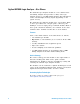
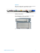
Agilent U4154A Logic Analyzer - At a Glance The U4154A logic analyzer module is a 136 channel state and timing analyzer that provides 2.5 Gb/s state logic analysis and up to 5.0 GHz timing analysis. The U4154A has 2 M to 200 M sample memory depth (depending on the option chosen). The U4154A logic analyzer module uses 4 pod cables. Each of these pod cables has 2 90- pin probe connector pods making it a total of eight pods per U4154A module.
Application This service guide applies to U4154A logic analyzer modules installed in a M9502A or M9505A AXIe chassis. U4154A Logic Analyzer Module The following figure displays the M9502A (2- slot) AXIe chassis and M9505A 5- slot AXIe chassis.
In This Service Guide This book is the service guide for the U4154A logic analyzer module. This service guide has five chapters. Chapter 1, “General Information” contains information about the module, lists accessories for the module, gives specifications and characteristics of the module, and provides a list of the equipment required for servicing the module. Chapter 2, “Preparing for Troubleshooting or Performance Testing” tells how to prepare the module for use.
Contents Agilent U4154A Logic Analyzer - At a Glance In This Service Guide 1 6 General Information Accessories 12 Probing Accessories 12 U4201A Pod Connector Cables Chassis and software Specifications 13 15 Preparing for Troubleshooting or Performance Testing To set up the U4154A module To test the U4154A module To clean the module 3 12 12 Characteristics 14 Environmental Characteristics 2 4 18 19 19 Testing U4154A Performance Perform the Self-Tests 24 Equipment Required for the Performance
Contents Test the U4154A Module 40 Configure the Logic Analysis System 41 Determine maximum clock rate 46 Adjust sampling positions using Eye Scan Re-align a stray channel 52 Test Pod 1 54 Test Pod 2 58 Test Pods 3 60 Performance Test Record 4 62 Calibrating Calibration Strategy 5 48 66 Troubleshooting To use the flowcharts 68 Self-Test Descriptions 70 PC Board Revision Test 70 Interface FPGA Version Test 70 Interface FPGA Register Test 70 FPGA to FPGA Communication Test 70 SPI Bus Communication T
Contents To remove the logic analyzer cable 86 To install the U4201A logic analyzer cable To replace the circuit board 87 87 To return the U4154A module or cable for Repair/Exchange 88 Index U4154A Logic Analyzer Service Guide 9
Contents 10 U4154A Logic Analyzer Service Guide
Agilent U4154A Logic Analyzer Service Guide 1 General Information Accessories 12 Chassis and software 12 Specifications 13 Characteristics 14 This chapter lists the accessories and some of the specifications and characteristics for testing and servicing the U4154A logic analyzer.
1 General Information Accessories One or more of the following accessories, sold separately, are required to set up and operate the U4154A logic analyzer module for testing and servicing it. Probing Accessories For information about probing accessories for logic analyzers with 90- pin pod connectors, see the Probing Solutions for Logic Analyzers Catalog, literature part number 5968- 4632E, available on Agilent’s web site (www.agilent.com).
General Information 1 Specifications The specifications are the performance standards against which the product is tested. U4154A Logic Analyzer Specifications Parameter 2.5 Gb/s mode Notes Maximum state data rate 2.5 Gb/s (DDR, 1.25 GHz clock), specified at probe tip. 1.4 Gb/s mode Maximum state data rate U4154A Logic Analyzer Service Guide 1.
1 General Information Characteristics The characteristics are not specifications, but are included as additional information. Table 1 14 Characteristics Characteristic Value Maximum Conventional Timing Rate 5.
General Information 1 Environmental Characteristics Table 2 Environmental Characteristics Probes Maximum Input Voltage ± 40 V, CAT I. CAT I = Category I, secondary power line isolated circuits. Operating Environment Temperature Instrument, 0 °C to 40 °C (+32 °F to 104 °F). Probe lead sets and cables, 0 °C to 65 °C (+32 °F to 149 °F). Humidity Instrument, probe lead sets, and cables, up to 80% relative humidity at +40 °C (+104 °F), non-condensing. Altitude To 3000 m (10,000 ft).
1 16 General Information U4154A Logic Analyzer Service Guide
Agilent U4154A Logic Analyzer Service Guide 2 Preparing for Troubleshooting or Performance Testing To set up the U4154A module 18 To test the U4154A module 19 To clean the module 19 This chapter gives you instructions for preparing the U4154A logic analyzer module for troubleshooting or servicing it. Operating Environment The operating environment is listed on page 15. Note the non- condensing humidity limitation. Condensation within the instrument can cause poor operation or malfunction.
2 Preparing for Troubleshooting or Performance Testing To set up the U4154A module To set up the U4154A module for troubleshooting/servicing, you first need to install it in one of the slots of the AXIe chassis. Then connect the chassis to the host PC via a PCIe link. On the host PC, install the Logic Analyzer (5.0 or higher) application to configure and control the U4154A module. Connect the U4154A module to a probe using the U4201A pod connector cables.
Preparing for Troubleshooting or Performance Testing 2 To test the U4154A module The U4154A logic analyzer module does not require an operational accuracy calibration or adjustment. After installing the module, you can test and use the module. • If you require a test to verify logic analyzer’s performance with the specifications, see “Testing U4154A Performance" on page 21. • If you require a test to verify correct module operation, see “To run the self tests" on page 74.
2 20 Preparing for Troubleshooting or Performance Testing U4154A Logic Analyzer Service Guide
Agilent U4154A Logic Analyzer Service Guide 3 Testing U4154A Performance Perform the Self-Tests 24 Equipment Required for the Performance Test 25 Assemble the SMA/Flying Lead Test Connectors 26 Set Up the Test Equipment 31 Connect the Test Equipment 35 Test the U4154A Module 40 Performance Test Record 62 This chapter tells you how to test the performance of the U4154A logic analyzer against the specifications listed on page 13.
3 Testing U4154A Performance sample of channels is tested. The calibration laboratory may choose to elaborate on these tests and test all channels at their discretion. NOTE A U4154A module that is licensed with the -01G option needs to be tested at an Agilent Service Center. The Service Center has the capability to test the module at up to the 2.5Gb/s state speed to ensure that the calibration will remain valid even after upgrading it to the -02G license.
Testing U4154A Performance 3 Test Record Description A Performance Test Record for recording the results of each procedure is provided in this chapter. You may want to make copies of this, and fill- in a copy each time you test the module. Test Equipment A list of the recommended test equipment is provided. You can use any equipment that satisfies the specifications given. However, the instructions are written with the presumption that you are using the recommended test equipment.
3 Testing U4154A Performance Perform the Self-Tests Once you have connected all the hardware components for the U4154A module and created a logical module for U4154A in the Agilent Logic Analyzer application, you are ready to run the self tests on U4154A. 1 Before performing the self- tests, disconnect all probes from the logic analyzer module. 2 Select Help->Self-Test... from the main menu. The Analysis System Self Tests window will appear. 3 In the Select suites list, select U4154A.
3 Testing U4154A Performance The progress of the self tests is displayed in the Results area of the window. 5 When the self- tests are complete, check the Results window to ensure that the Result Summary says that all tests passed. If all tests did not pass, refer to “To use the flowcharts" on page 68. 6 Select the Close button to close the Analysis System Self Tests window.
3 Testing U4154A Performance Assemble the SMA/Flying Lead Test Connectors The SMA/Flying Lead test connectors provide a high- bandwidth connection between the logic analyzer and the test equipment. The following procedure explains how to fabricate the four required test connectors. Table 4 Materials Required for SMA/Flying Lead Test Connectors Material Critical Specification SMA Board Mount Connector (Qty 8) Recommended Model/Part Johnson 142-0701-801 (see www.johnsoncomponents.
Testing U4154A Performance 3 1 Prepare the pin strip header: a Cut or cleanly break a 2 x 2 section from the pin strip. b Trim about 1.5 mm from the pin strip inner leads and straighten them so that they touch the outer leads. c Trim about 2.5 mm from the outer leads. d Using a very small amount of solder, tack each inner lead to each outer lead at the point where they are touching.
3 Testing U4154A Performance 2 Solder the pin strip to the SMA board mount connector: a Solder the leads on the left side of the pin strip to the center conductor of the SMA connector as shown in the diagram below. b Solder the leads on the right side of the pin strip to the inside of the SMA connector’s frame as shown in the diagram below. Use a small amount of solder.
Testing U4154A Performance 3 strip, and the center conductors of each SMA connector. b Ensure that there is continuity between each of the two pins on the right side of the pin strip, and the SMA connector frames. c Ensure that there is NO continuity between the SMA connector center conductor and the SMA connector frame (ground). 5 Finish creating the test connectors: a Attach an SMA m- m adapter to one end of each of the four SMA/Flying Lead test connectors.
3 Testing U4154A Performance c The finished test connector is shown in the pictures below.
Testing U4154A Performance 3 Set Up the Test Equipment This section explains how to set up the test equipment for the minimum master- to- master clock time/maximum state data rate test. 1 Turn on the required test equipment. Let all of the test equipment and the logic analyzer warm up for 30 minutes before beginning any test. 2 Set up the pulse generator according to one of the following tables.
3 Testing U4154A Performance Table 5 81134A Pulse Generator Setup Main Channel 2 Channel 1 Trigger Mode: Pulse/Pattern Mode: Square ÷ 1 Mode: Square ÷ 1 Disable Freq: set in previous step. Timing Timing Clock Internal Delay Ctrl Input Off Delay Ctrl Input Off Width: (not available in square mode) Width: (not available in square mode) Table 6 Pulse Perf: Normal Pulse Perf: Normal Deskew: 0 ps Deskew: 0 ps Levels: Normal, Custom Levels: Normal, Custom Ampl: 0.45 V Ampl: 0.
Testing U4154A Performance 3 3 Set up the oscilloscope. a Set up the oscilloscope according to one of the following tables. Table 7 DSO90604A Oscilloscope Setup Setup: Channel 1 Setup: Channel 2 Setup: Channel 3 Setup: Channel 4 On On Off Off Scale: 50 mV/div Scale: 50 mV/div Offset: 600 mV Offset: 600 mV Skew: (Set later. See page 39.) Skew: 0.
3 Testing U4154A Performance Table 8 54855A Oscilloscope Setup Setup: Channel 1 Setup: Channel 2 Setup: Channel 3 Setup: Channel 4 On On Off Off Scale: 100 mV/div Scale: 100 mV/div Offset: 600 mV Offset: 600 mV Skew: (Set later. See page 39.) Skew: 0.
Testing U4154A Performance 3 Connect the Test Equipment Connect the U4154A Logic Analyzer Pod to the Pulse Generator 1 Connect Transition Time Converters (if required - see page 25) to each of the four outputs of the pulse generator: Channel 1 OUTPUT, Channel 1 OUTPUT, Channel 2 OUTPUT, Channel 2 OUTPUT.
3 Testing U4154A Performance 6 Connect the Pod 1 E5382A Flying Lead Probe Set’s CLK lead to the pin strip of the SMA/Flying Lead connector at the pulse generator’s Channel 1 OUTPUT.
Testing U4154A Performance 3 Connect the Pulse Generator Output to the Oscilloscope 1 Attach Male BNC to Female SMA adapters to Channels 1 and 2 on the oscilloscope. 2 Attach one end of an SMA cable to the Male BNC to Female SMA adapter on Channel 1 of the oscilloscope. 3 Attach the other end of the SMA cable to the SMA/Flying Lead connector at the Channel 2 OUTPUT of the pulse generator. 4 Attach one end of the other SMA cable to the Male BNC to Female SMA adapter on Channel 2 of the oscilloscope.
3 Testing U4154A Performance Verify and adjust the pulse generator DC offset 1 From the oscilloscope’s main menu, choose Measure > Markers.... 2 In the Markers Setup dialog, select the Manual Placement mode; then, set marker “Ay” to 475 mV, and set marker “By” to 725 mV. 3 Observe the waveforms on the oscilloscope display. If they are not centered within the “Ay” and “By” markers, adjust the pulse generator’s Channel 2 OFFSET until the waveforms are centered as well as possible.
3 Testing U4154A Performance Deskew the oscilloscope This procedure neutralizes any skew in the oscilloscope’s waveform display. 1 On the oscilloscope, make sure the Horizontal scale is 200 ps/div. You can do this using the knob in the Horizontal setup section of the front panel. 2 Select Setup from the menu bar at the top of the display. 3 Select Channel 1.
3 Testing U4154A Performance Test the U4154A Module The following sections explain how to test the maximum state data rate. 1 Record the U4154A logic analyzer’s model and serial number in the Performance Test Record (see page 62). Record your work order number (if applicable) and today’s date. 2 Record the test equipment information in the “Test Equipment Used” section of the Performance Test Record. 3 Turn on the AXIe chassis.
3 Testing U4154A Performance Configure the Logic Analysis System 1 In the Agilent Logic Analyzer application, choose File→New. This puts the logic analysis system into its initial state. 2 Disable all logic analyzers other than the analyzer under test. a Select the Overview tab at the bottom of the main window. b Click on each unused logic analyzer and select disable. Only the logic analyzer to be tested should remain enabled.
3 Testing U4154A Performance 3 Set up the bus and signals: a In the Overview window, select Setup→Bus/Signal... from the module’s drop- down menu. b In the Analyzer Setup window, choose the Threshold NOTE 42 button for Pod 1. The E5382A probe must be connected to the logic analyzer pod as described on page 35.
Testing U4154A Performance 3 The Threshold Settings window appears. c Set the threshold value for Pod 1 of the logic analyzer to 600 mV. Click Apply to All Other Pods (Excluding Clocks). Then, click Done to close the dialog. d Drag the scroll bar all the way to the left.
3 Testing U4154A Performance e Select the Clock Thresholds button. f In the Threshold Settings for Clock Channels dialog, set the Pod 1 clock threshold to Differential. g Click Done. The activity indicator will show activity on clock 1.
3 Testing U4154A Performance h The activity indicators now show activity on the channels that are connected to the pulse generator. Un- assign all channels. You can do this quickly by clicking on the left- most check mark and dragging to the right across all of the other check marks. i Click to select channels 2, 6, 10, and 14 as shown in the picture above. 4 Select the State sampling mode and set the State Clock options: a Select the Sampling tab of the Analyzer Setup window.
3 Testing U4154A Performance Determine maximum clock rate 1 Switch to the Listing window by selecting the Listing tab at the bottom of the main window. 2 Click the Run Repetitive toolbar button to start a repetitive run on the logic analyzer for acquiring data repeatedly. Acquired data will start appearing in the Listing window. 3 Start increasing the frequency on the pulse generator by 1 MHz increments while simultaneously observing the logic analyzer data acquisition status.
3 Testing U4154A Performance Determine PASS/FAIL for the Pulse Generator Frequency test If you get 100 acquisitions without any error display at a pulse generator frequency (including uncertainty) greater than 1250 MHz, then the logic analyzer passes this portion of the test. For example, a frequency of 1280 MHz - 2% uncertainty = 1254.4 MHz indicates a PASS result for the test. Record PASS/FAIL result of this test in the “Pulse Generator Frequency Test” section of the Performance Test Record (page 62).
3 Testing U4154A Performance Adjust sampling positions using Eye Scan 1 Select the Eye Scan: Sample Positions and Thresholds... button. The Eye Scan - Sample Positions and Threshold Settings dialog will appear. 2 In the Buses/Signals section of the dialog, ensure that the check box next to “My Bus 1” is checked. 3 Set the sample position for My Bus 1 signals by dragging the blue bar for “My Bus 1” to approximately - 3.6 ns.
Testing U4154A Performance 3 4 Click the plus sign to expand bus “My Bus 1”.
3 Testing U4154A Performance NOTE Align the blue bars vertically Initially, the blue bars will be vertically aligned. After running Eye Scan, the blue bars will not be vertically aligned because an independent sample position will be determined for each channel. 1 If the blue bars in the Eye Scan display are not vertically aligned: a In the “My Bus 1” row, grab the right-most blue bar with the mouse pointer and move it all the way to the left. Release the mouse button.
3 Testing U4154A Performance 6 Select Do full time/voltage scan as the scan dimension. 7 Select the Lock thresholds checkbox and click OK. 8 Select the Run This Measurement button in the Eye Scan - Sample Positions and Threshold Settings dialog. 9 Ensure that an eye appears for each bit near the recommended starting position. Depending on your test setup, the eye position may vary.
3 Testing U4154A Performance Re-align a stray channel If the blue bar for a particular bit does not appear in its eye near the recommended starting position, then do the following steps to realign the sampling position of the stray channel. In the following example, the sampling position of one channel (My Bus 1 [0]) must be realigned with the sampling position of the other channels.
3 Testing U4154A Performance 1 Using the mouse, drag the sample position (blue line) of the stray channel (channel “My Bus 1 [0]” in the above example) so that it is in the same eye as the other channels. The Suggested Position from Eye Scan (green triangle) will also move to the new eye. 2 Repeat the above step for all the remaining stray channels. 3 Click the Run This Measurement button in the Eye Scan - Sample Positions and Threshold Settings dialog.
3 Testing U4154A Performance Test Pod 1 The steps that follow include pass/fail criteria. Determine PASS/FAIL (1 of 2 tests) 1 PASS/FAIL: If an eye exists near - 3.6 ns for every bit, and Eye Scan places a blue bar in the narrow eye for each bit, then the logic analyzer passes this portion of the test. Record the result in the “Eye Scan locates an eye for each bit” section of the Performance Test Record (page 62). 2 If an eye does not exist near - 3.
3 Testing U4154A Performance Close the Eye Scan and Analyzer Setup Windows 1 Select OK to close the Eye Scan - Sample Positions and Threshold Settings dialog. 2 Select OK to close the Analyzer Setup window. Configure the markers Data must be acquired before the markers can be configured. Therefore, you need to run the analyzer to acquire data. 1 Switch to the Listing window by selecting the Listing tab at the bottom of the main window. 2 Select the Run icon .
3 Testing U4154A Performance 4 From the Main Menu, choose Markers→New. a You can accept the default name for the new marker. b Change the Position field to Value. c Select the Occurs... button and create the marker setup shown below. Click here to add event Click here to select “Or” 5 In the Value window, select the Properties... button. 6 In the Value Properties window, select Stop repetitive run when value is not found. 7 Select OK to close the marker Value Properties window.
3 Testing U4154A Performance Determine PASS/FAIL (2 of 2 tests) Pass/Fail Point: The Listing window is set up to search for the appropriate number of A's and 5's in the acquisition. If the logic analyzer does not detect the correct number of A’s and 5’s, an error window will appear. 1 Select the Run Repetitive icon . Let the logic analyzer run for about one minute. The analyzer will acquire data and the Listing Window will continuously update.
3 Testing U4154A Performance Test the complement of the bits Now test the logic analyzer using inverted levels (in other words, complement data). 1 On the pulse generator, in the PULSE setup for CHANNEL 2, select inverted levels: • On the 81134A pulse generator, select Levels: Inverted. • On the 8133A pulse generator, select COMP (LED on). 2 Verify the DC offset and adjust it if necessary. See page 38. 3 Adjust the sampling positions (run Eye Scan). See page 48. 4 Determine pass or fail (1 of 2 tests).
3 Testing U4154A Performance 8 Assign bits 2, 6, 10, and 14 of Pod 2. 9 Adjust the sampling positions using Eye Scan. Be sure to expand “My Bus 1” and use the recommended starting position noted on page 48. Realign any stray channels if necessary. See page 52. 10 Determine pass or fail (1 of 2 tests). See page 54. 11 Select OK to close the “Analyzer Setup” window. 12 Switch to the Listing window by selecting the Listing tab at the bottom of the main logic analyzer window.
3 Testing U4154A Performance Test Pods 3 1 Disconnect the E5382A Flying Lead Probe Set from Pod 2 and connect it to Pod 3 of the logic analyzer. (The clock input on Pod 1 is used when testing Pod 3.) 2 In the Buses/Signals setup dialog, set the Pod 1 clock threshold to Differential: a Drag the scroll bar all the way to the left. b Select the Clock Thresholds button. c In the Threshold Settings for Clock Channels dialog, set the Pod 1 clock threshold to Differential. Click Done.
Testing U4154A Performance 3 The activity indicator will show activity on clock 1. 3 Set the State Clock options: a For State Clock, select Pod 1 Clock and Both edges. 4 Perform the normal and complement tests for Pod 3, changing the connection to the pod, setting thresholds, making channel assignments, etc., as appropriate. Repeat the above steps for testing pods 4 to 8. Upon completion, the logic analyzer is completely tested.
3 Testing U4154A Performance Performance Test Record LOGIC ANALYZER MODEL NO. (circle one): U4154A Logic Analyzer Serial No. Work Order No. Date: Recommended Test Interval - 2 Year/4000 hours Recommended next testing: TEST EQUIPMENT USED Pulse Generator Model No. Oscilloscope Model No. Pulse Generator Serial No. Oscilloscope Serial No. Pulse Generator Calibration Due Date: Oscilloscope Calibration Due Date: MEASUREMENT UNCERTAINTY Clock Rate Pulse Generator Frequency Accuracy: 81134A: ±0.
Testing U4154A Performance 3 TEST RESULTS Normal Complement Normal Complement Pod 3 Results (pass/fail): Pod 4 Results (pass/fail): Pod 5 Results (pass/fail): Pod 6 Results (pass/fail): Pod 7 Results (pass/fail): Pod 8 Results (pass/fail): U4154A Logic Analyzer Service Guide 63
3 64 Testing U4154A Performance U4154A Logic Analyzer Service Guide
Agilent U4154A Logic Analyzer Service Guide 4 Calibrating Calibration Strategy 66 This chapter gives you instructions for calibrating the U4154A logic analyzer.
4 Calibrating Calibration Strategy The U4154A logic analyzer does not require any periodic adjustments or calibration by the user to ensure operational accuracy. However, Agilent recommends that performance of the U4154A logic analyzer be tested against its specifications at two- year intervals. This testing is required in order to obtain calibration certification.
Agilent U4154A Logic Analyzer Service Guide 5 Troubleshooting To use the flowcharts 68 To run the self tests 74 Self-Test Descriptions 70 To exit the test system 75 To test the cables 76 This chapter provides instructions for troubleshooting a U4154A module that is not operating correctly. The troubleshooting consists of flowcharts, self- test instructions, and a cable test. If you suspect a problem, start at the top of the first flowchart.
5 Troubleshooting To use the flowcharts Flowcharts are the primary tool used to isolate defective assemblies. The flowcharts refer to other tests to help isolate the problem. The circled numbers on the charts indicate connections with the other flowchart. Start your troubleshooting at the top of the first flowchart.
Troubleshooting Figure 2 5 Troubleshooting Flowchart 2 U4154A Logic Analyzer Service Guide 69
5 Troubleshooting Self-Test Descriptions The self- tests for U4154A logic analyzer identify the correct operation of major functional areas in the U4154A module. PC Board Revision Test This tests that the FPGA is communicating with the backplane and that the board under test is a supported version. Interface FPGA Version Test This test verifies that the FPGA program is a version that the software can use.
5 Troubleshooting • That individual locations can be independently addressed. • The EEPROM can be block erased. Probe ID Read Test The purpose of this test is to verify that the Probe ID values can be correctly read and to verify the functionality of the Digital to Analog Converter by testing the two Probe ID DAC outputs at various voltage levels.
5 Troubleshooting This test uses the pod, bonus, and calibration DACs, the calibration oscillator (implemented in the interface FPGA), the comparators, the connections between the comparators and the Analysis chip, and the activity indicators in the Analysis chip. We verify that we can use the DACs to control the data input to the comparators. We verify that each comparator data channel produces output. We verify that each comparator output is connected to each ASIC data input.
Troubleshooting 5 ATB (AXIe Trigger Bus) Test This test verifies the ATB signal connections between the acquisition chips, the interface FPGA and the two 8- bit transceiver chips.
5 Troubleshooting To run the self tests You can run self tests on the U4154A module to verify if the module is operating correctly. Before running self tests, ensure that: • you have connected all the hardware components for the U4154A module • created a logical module for U4154A in the Agilent Logic Analyzer application. • disconnected all probes from the logic analyzer module. You use the Analysis System Self Tests window to run self tests.
Troubleshooting 5 If all tests did not pass, refer to “To use the flowcharts" on page 68. To exit the test system 1 Close the self- test window. No additional actions are required.
5 Troubleshooting To test the cables This test allows you to functionally verify U4201A logic analyzer cables and Agilent E5379A probes. Table 9 Equipment Required to Test Cables Equipment Critical Specification Recommended Part Stimulus Board No Substitute 16760-60001 Differential Probes No Substitute E5379A (Qty 2) 1 Connect the U4154A logic analyzer to the stimulus board. a Connect the Agilent E5379A 90- pin differential probes to the logic analyzer cable (also called “Pods”) to be tested.
5 Troubleshooting 2 Set up the stimulus board a Configure the oscillator select switch S1 according to the following settings: • S1 0 (Off). • S2 1 (On). • S3 0 (Off). • Int. b Configure the data mode switch S4 according to the following settings: • Even. • Count. c Press the Resynch VCO button, then the Counter RST (Counter Reset) button. 3 In the Agilent Logic Analyzer application, choose File→New. This puts the logic analysis system into its initial state.
5 Troubleshooting 4 Disable all analyzers except the one being tested. This simplifies the instructions and makes module initialization faster. a Select the Overview tab at the bottom of the main window. b Click on each unused logic analyzer and select disable. Only the logic analyzer to be tested should remain enabled.
Troubleshooting 5 5 Set up the bus: a In the Overview window, select Setup -> Bus/Signal... from the module’s drop- down menu. b Scroll if necessary to view the pods you are testing. c Verify that the pod threshold buttons say “Threshold: Differential”, as shown above. If they don’t, make sure the correct probes (E5379A) are attached to pods 1 and 2. The threshold is set to Differential automatically when E5379A probes are attached.
5 Troubleshooting d Channels 7 through 0 are already assigned by default. Assign pod 2 channels 15 through 0 and pod 1 channels 15 through 8 by clicking and dragging from the left- most channel box to the right- most channel box. Your display should look like the lower picture when you are done. 6 Select the State sampling mode and set the State Clock options: a Select the Sampling tab of the Analyzer Setup window. b Select State - Synchronous Sampling.
5 Troubleshooting 8 Adjust sampling positions: a Select the Eye Scan: Thresholds and Sample Positions button. The Eyescan - Sample Positions dialog will appear. b In the “Buses/Signals” section of the Eyescan - Sample Positions dialog, make sure the check box next to “My Bus 1” is checked. c Click Edit and select the Do time scan only option as the scan dimension and the Lock Thresholds checkbox. d Select the Run This Measurement button in the Eyescan - Sample Positions dialog.
5 Troubleshooting e Make sure the sampling positions are set properly, and re- align any stray channels if necessary. f Select OK to close the Eyescan - Sample Positions window. g Select OK to close the Analyzer Setup window. 9 Switch to the Listing window by selecting the Listing tab at the bottom of the main window. 10 Select the Run icon . The listing should look similar to the figure below when you scroll down a bit. Scroll down at least 256 samples to verify the data.
5 Troubleshooting the stimulus board’s pod 5 connector — just using different probes. b Select the Run icon . If the failure is the same (that is, the error follows the cable) then the cable is faulty. If the failure switches pods (that is, the error follows the E5379A probe) the probe is faulty. 12 Repeat the cable test for pods 3 and 4: a Connect the logic analyzer’s pod 3 cable to the stimulus board’s pod 4 connector.
5 84 Troubleshooting U4154A Logic Analyzer Service Guide
Agilent U4154A Logic Analyzer Service Guide 6 Returning and Replacing a U4154A Module or its cables To remove the U4154A module 86 To remove the logic analyzer cable 86 To install the U4201A logic analyzer cable 87 To replace the circuit board 87 To return the U4154A module or cable for Repair/Exchange 88 This chapter contains the instructions for removing and replacing the U4154A logic analyzer module, and the probe cables of the module as well as the instructions for returning defective parts to Agilent
6 Returning and Replacing a U4154A Module or its cables To remove the U4154A module If the U4154A module or any of its parts are faulty, remove the faulty module from the AXIe chassis, return it to Agilent Technologies for repair/exchange. On getting a replaced module, install it in the AXIe chassis. Instructions for removing or installing the module into the AXIe chassis can be found in the U4154A Logic Analyzer Installation Guide.
6 Returning and Replacing a U4154A Module or its cables To install the U4201A logic analyzer cable Perform the following steps to connect the new/replaced logic analyzer cable to the front panel of the U4154A module. 1 Attach cable connector to the pod input on the front panel of the module. 2 Tighten the two thumb screws on both sides of the U4201A cable to retain the cable tightly inside the relevant pod input. Do not over tighten the thumb screws.
6 Returning and Replacing a U4154A Module or its cables To return the U4154A module or cable for Repair/Exchange Before returning the U4154A module or a logic analyzer cable to Agilent Technologies, contact your nearest Agilent Technologies Sales Office for additional details. Information on contacting Agilent can be found at www.agilent.com. 1 Write the following information on a tag and attach it to the module/cable. • Name and address of owner. • Model number. • Serial number.
Index A M accessories, 12 acquisition, 70 Agilent,contact information, 4 module clean, 19 remove, 86 test, 19 multi-card module test, 22 C cable install, 87 remove, 86 test E5379A cable, 76 calibrating see also testing performance calibration, 65 strategy, 66 characteristics, 14 environmental, 15 chassis, 12 circuit board replace, 87 clean module, 19 cleaning the instrument, 3 connectors, test, 26 contacting Agilent, 4 E environment characteristics, 15 operating, 17 equipment test, 23 eye finder adjust
Index 90 U4154A Logic Analyzer Service Guide