Agilent U4154A Logic Analyzer Installation Guide Agilent Technologies
Notices © Agilent Technologies, Inc. 2011 Warranty Manual Notices No part of this manual may be reproduced in any form or by any means (including electronic storage and retrieval or translation into a foreign language) without prior agreement and written consent from Agilent Technologies, Inc. as governed by United States and international copyright laws. The material contained in this document is provided “as is,” and is subject to being changed, without notice, in future editions.
Safety Information Agilent Technologies certifies that this product met its published specifications at the time of shipment from the factory. Agilent Technologies further certifies that its calibration measurements are traceable to the United States National Institute of Standards and Technology to the extent allowed by that organization's calibration facility, and to the calibration facilities of other International Standards Organization members.
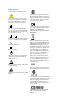
Safety Symbols Products display the following symbols: ! If you see this symbol on a product, you must refer to this guide for specific Warning or Caution information to avoid personal injury or damage to the product. Indicates the field wiring terminal that must be connected to ground before operating the equipment. Protects against electrical shock in case of fault. The CSA mark is a registered trademark of the Canadian Standards Association and indicates compliance to the standards laid out by them.
Contents 1 Introduction U4154A Logic Analyzer Module 8 Features included in the U4154A Logic Analyzer Module U4154A Module Components 9 AXIe Chassis 11 AXIe Embedded System Module (ESM) Host PC 2 11 13 Pod Connector Cables Probes 8 14 16 Setting up the Hardware for U4154A Step 1 - Inspect the Module Shipment 18 Step 2 - Install the U4154A Module in the AXIe Chassis 20 To insert the U4154A module into the chassis 20 To remove the U4154A module from the chassis 21 To install multiple U4154A modules
3 Installing Software Components Hardware and Software Requirements 42 Installing Agilent Logic Analyzer Software Verifying the Installation 43 43 Upgrading Chassis Firmware 44 Step 1 - Connect the AXIe chassis to a Network 46 Step 2 - Configure an FTP Server 46 Step 3 - Extract the contents of the firmware upgrade package to the FTP server 47 Step 4 - Perform the firmware upgrade 47 Step 5 - Restart the chassis and host PC 52 Step 6 - Verify the firmware upgrade 53 Upgrading U4154A Module’s Interface
Agilent U4154A Logic Analyzer Installation Guide 1 Introduction U4154A Logic Analyzer Module 8 AXIe Chassis 11 Host PC 13 Pod Connector Cables 14 Probes 16 This chapter introduces you to the U4154A Logic Analyzer module and other hardware components such as the AXIe chassis and host PC that are required in the module setup. The chapter also describes the U4154A module’s components.
1 Introduction U4154A Logic Analyzer Module The Agilent U4154A Logic Analyzer is an instrument module installed in one of the module slots of an Agilent AXIe chassis (M9502A portable 2- slot chassis or M9505A 5- slot chassis). U4154A is a 136 channel AXIe based high speed state and timing logic analyzer. It provides measurement capabilities, probing, and application support and analysis tools for digital testing and debugging.
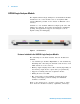
Introduction 1 U4154A Module Components The U4154A module connects to a System Under Test (SUT) via pod connector cables and probes to make real- time measurements. The following figure displays the front panel of the U4154A module with its various components labelled. Out of Service LED Module Description Logic Analyzer POD POD Label Module Insertion/Extraction Handle Retaining Screw Figure 2 U4154A module As displayed in Figure 2, the U4154A module has the following components.
1 Introduction Component Description Module Insertion/Extraction Handles The handles on both sides of the module to insert or eject the module from the slot of the AXIe chassis. Serial Number (on top of module) Uniquely identifies the U4154A module. When contacting Agilent support, report this number so that any manufacturing information or past servicing associated with the module can be noted. The serial number is also provided in a Code 128 bar code for inventory purposes.
1 Introduction AXIe Chassis The Agilent AXIe chassis is a modular instrument chassis that supports complex and high density testing. The chassis provides slots for installing multiple instrument modules such as the U4154A module. Besides providing a frame for the installation of the U5154A module, the AXIe chassis also provides power supply, cooling system, PCI Express (PCIe) Gen 2 data bus, Gigabit LAN hub, local bus for module- to- module signaling, and host PC connections to U4154A.
1 Introduction The ESM: • tracks inserted modules and manages power requirements. • monitors chassis temperature and controls variable- speed chassis fans. • monitors module sensors and reports component failures to a system log. • acts as a Gigabit Ethernet switch; forwards frames along the backplane. • connects an external host PC to the chassis. • synchronizes timing across all modules through the Agilent Trigger Bus, using an internal or external clock source.
1 Introduction Host PC A host PC is a laptop or a desktop PC with a PCIe interface. This PC is used to host all the required software components of the U4154A module for configuring, controlling, and using this module. You can connect the host PC to the Agilent AXIe chassis using the PCIe x8 interface. Refer to the Agilent M9502A/M9505A AXIe Chassis Startup Guide to get more information on a host PC that can connect to AXIe chassis.
1 Introduction Pod Connector Cables The Agilent U4201A 90- pin pod connector cable is used to connect the U4154A module with the probes which then connect to the DUT/SUT. The module connector at one end of the cable is installed in the relevant pod input on the front panel of the Logic Analyzer module. The other end of the cable is connected to the probes.
Introduction 1 Figure 6 U4201A 90-pin Pod Connector Cable connected to Differential Soft Touch and Flying Lead Set Probes Refer to the topic “Step 6 - Connect the U4154A Module to Probes" on page 36 to know how to connect the U4154A Module with probes using the U4201A cables.
1 Introduction Probes Probing is the key to effective and efficient use of the U4154A logic analyzer module. Agilent Technologies offers a wide variety of probing accessories that support general- purpose and application- specific measurement needs. Agilent Technologies provides reliable, electrically and mechanically unobtrusive probes that make it easy to connect your U4154A logic analyzer to your system under test. For more information on Agilent probes: • Go to www.agilent.
Agilent U4154A Logic Analyzer Installation Guide 2 Setting up the Hardware for U4154A Step 1 - Inspect the Module Shipment 18 Step 2 - Install the U4154A Module in the AXIe Chassis 20 Step 3 - Set up the Agilent AXIe Chassis 29 Step 4 - Connect the AXIe Chassis to Host PC 30 Step 5 - Connect the Host PC and AXIe Chassis to a Network 31 Step 6 - Connect the U4154A Module to Probes 36 Step 7 - Connect the Probes to the DUT 37 Step 8 - Power up the connected hardware components 38 Step 9 - Verify the Hardware
2 Setting up the Hardware for U4154A Step 1 - Inspect the Module Shipment What’s Included in the Module Shipment Unpack and verify the shipment contents to check if you have received all the items that you ordered. The shipment should contain the following items. However, the shipping list delivered with the shipment should supersede this list. Item Description U4154A Module The instrument module that you install in one of the slots of Agilent AXIe chassis.
2 Setting up the Hardware for U4154A To check the warranty information on your U4154A module, go to www.agilent.com/find/warranty and specify the module’s model number (U4154A) in the Product Number field, and specify the serial number from the top of the module in the Serial No. field.
2 Setting up the Hardware for U4154A Step 2 - Install the U4154A Module in the AXIe Chassis The AXIe chassis and U4154A module come in separate shipments. The module is not pre- installed in the chassis. This step involves carefully inserting the U4154A module in an empty slot of an Agilent AXIe chassis. The slots are identified by the slot numbers written on the front panel of the chassis.
Setting up the Hardware for U4154A 2 6 Tighten the retaining screws on either end of the U4154A module to ensure the ground connection. After you have installed the U4154A module in the chassis, ensure that you insert a filler module in any empty slot(s) of the chassis. Do not operate the chassis with empty slots. This is especially important for the slots on either side of the U4154A module. This allows proper air flow and cooling, and provides EMI shielding for the chassis and installed components.
2 Setting up the Hardware for U4154A 3 Remove the module: Open the module insertion/extraction handles by pivoting them out towards you. This unseats the module from the chassis backplane. 4 Use the module insertion/extraction handles to pull the module out from the chassis. CAUTION Do not remove the AXIe ESM, which is integral to the operation of the chassis. AXIe ESM that needs servicing is to be removed by Agilent personnel only.
2 Setting up the Hardware for U4154A NOTE CAUTION Turn off the AXIe chassis and host PC power before removing, replacing, or installing modules. When removing modules that are connected together as multiple-card modules, be sure to eject the multiple modules simultaneously, otherwise, the flex cables and/or connectors could be damaged. The enclosure surface of the U4154A module may become hot during use.
2 Setting up the Hardware for U4154A 2 Place the bolt (removed in step1) in its marked middle location on the top cover of the module. Hand tighten the bolt. 3 Perform step1 and 2 for all the U4154A modules that you want to include in the multi- card set except the module that you want to keep as the top most module in the set. 4 Turn the U4154A module (that you plan to keep second from the bottom in the set) upside down.
Setting up the Hardware for U4154A 2 5 Attach the other flex cable to the opposite under- side connector of the second module. 6 Now, align the second module (with the flex cables attached) on top of the first (lower) module.
2 Setting up the Hardware for U4154A 7 The top side of the U4154A module has two connectors to connect the other end of the two flex cables. Attach the other end of the flex cables to these connectors on the top side of the first (lower) module. Be careful not to bend the flex cables any more than is necessary to fit between the module connectors. 8 Repeat steps 4 to 7 for the remaining U4154A modules that you want to include in the multi- card set. 9 Align the set of connected U4154A modules.
2 Setting up the Hardware for U4154A 10 Insert the aligned set of modules into the AXIe chassis, seat them, lock the module insertion/extraction handles, and tighten the retaining screws. 11 To verify that the flex cables are installed correctly, run the self test named Resource Bus Connection Test in the Agilent Logic Analyzer GUI. Refer to the Agilent Logic Analyzer Online Help to know how to run self tests.
2 Setting up the Hardware for U4154A If the test results indicate that a flex cable is not seated correctly in the connector, repeat the flex cable attachment steps, and run the test again.
2 Setting up the Hardware for U4154A Step 3 - Set up the Agilent AXIe Chassis If you are using the U4154A module in a portable application, then retain the plastic bumpers and carry handle(s) that ship with the chassis for benchtop use. If you are using the module in a rack mounted configuration, remove the bumpers and carry handle(s) from the chassis, attach the rackmount brackets, and mount onto a rack.
2 Setting up the Hardware for U4154A Step 4 - Connect the AXIe Chassis to Host PC The host PC is typically a laptop PC with an ExpressCard PCIe adapter or a desktop PC with a PCIe interface. Using the PCIe interface Connect the host PC to the PCI Express Gen1/Gen2 x8 port located on the front panel of the AXIe chassis ESM via a PCIe cable. NOTE It is recommended that you turn off the standby mode and disable hibernation on the host PC connected to the AXIe chassis.
Setting up the Hardware for U4154A 2 Step 5 - Connect the Host PC and AXIe Chassis to a Network Besides connecting the host PC to the AXIe chassis via the PCIe interface, you also connect the host PC and chassis to a common network. The connectivity of chassis to a network is required to allow ESM to communicate on a network common to the host PC and to perform the firmware upgrade process on the chassis.
2 Setting up the Hardware for U4154A Single chassis scenario The following figure illustrates the connectivity of host PC and chassis to the network when you are using a single AXIe chassis with a single host PC. Figure 8 Connecting a single chassis and a host PC to a network In this scenario, the connectivity of the host PC and chassis to a common network is highly recommended for the firmware upgrades but not mandatory.
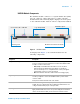
Setting up the Hardware for U4154A 2 • the Intel PRO/1000 PL network connection is not used. Therefore, disable the Intel PRO/1000 PL network adapter using the Device Manager. (This is preferred.) Multiframe scenario with one chassis per host PC The following figure illustrates the connectivity of host PC and chassis to a network when you are using multiple AXIe chassis (multiframe scenario). In this scenario, there is one host PC for each chassis connected via PCIe interface.
2 Setting up the Hardware for U4154A Figure 9 Connecting multiple chassis and host PCs to a network (One chassis per host PC) This is the recommended scenario when using multiple chassis. In this scenario, the connectivity of the chassis to a network is highly recommended but not mandatory. However, host PC must be connected to a network. If you do not want to connect the chassis to a network, you can use the Intel PRO/1000 PL network connection.
Setting up the Hardware for U4154A 2 Figure 10 Connecting multiple chassis and host PCs to a network (Multiple chassis per host PC) In this scenario, the connectivity of the chassis and host PC to a common network is mandatory. Each chassis and host PC must be connected to a common network. The Intel PRO/1000 PL network connection is not used in this scenario.
2 Setting up the Hardware for U4154A Step 6 - Connect the U4154A Module to Probes In this step, you use the U4201A pod connector cables shipped with the U4154A module to connect the module to probes. Tighten the thumb screws on the U4201A cables to connect the cable to the relevant pod input on the front panel of the U4154A module. Then connect the other end of the cable to the probe. CAUTION - Do not over tighten the thumb screws. Hand tightening is recommended or maximum torque of 3in-lb.
Setting up the Hardware for U4154A 2 Step 7 - Connect the Probes to the DUT As per the testing scenario, use the appropriate probe from the probing solutions available with Agilent. You can use: • Flying- lead probe sets. This is called general purpose probing. In this probing, connect probe connectors to individual IC pins or test points. • Elastomeric probe adapter and 1/4 flex adapter products available for several types of QFP packages. This is called QFP package probing.
2 Setting up the Hardware for U4154A Step 8 - Power up the connected hardware components Power up all the connected hardware components in the U4154A setup. 1 The U4154A module uses the power supplied by the AXIe chassis in which it is installed. The AXIe chassis power cord comes with the chassis shipment. Insert the power cord into the inlet at the rear of the chassis. 2 Connect the cord to an appropriate AC power main. 3 Push the circuit breaker to the right, which is the ON position.
Setting up the Hardware for U4154A 2 Step 9 - Verify the Hardware Setup After powering ON the connected hardware components, you can verify if you have correctly set up the hardware if: • a steady green status light is displayed on the ESM of the AXIe chassis. • the Out of Service (OOS) LED on the front panel of the U4154A module turns off. If the chassis does not power up to a steady green Status light, or powers up to a steady red light, the chassis has detected a failure and requires service.
2 Setting up the Hardware for U4154A Sample Hardware Setup Figure 11 U4154A module in Agilent AXIe chassis Figure 11 displays a sample setup of the U4154A module. The module is installed in slot 2 of Agilent M9502A portable 2- slot AXIe chassis. A filler panel module is installed in slot 1 of the chassis. A laptop is used as a host PC and connected to the ESM of the chassis via a PCIe cable. Three U4201A cables are used to connect the U4154A module pods to Agilent E5845A probes.
Agilent U4154A Logic Analyzer Installation Guide 3 Installing Software Components Hardware and Software Requirements 42 Installing Agilent Logic Analyzer Software 43 Upgrading Chassis Firmware 44 Upgrading U4154A Module’s Interface FPGA 54 Installing Additional Software Packages 57 Setting up Communication between the Host PC and ESM of AXIe chassis 58 Once the hardware setup for the U4154A module is ready, you need to install the software components of U4154A on the designated host PC.
3 Installing Software Components Hardware and Software Requirements The following are the hardware and software requirements that should be met on the host PC before the installation of software components on this PC: Hardware requirements • PCIe interface x8 (Gen1 and Gen2 compliant) • Pentium® processor 1 GHz or equivalent • 512 MB available RAM • VGA resolution 1024 x 768 • 5 GB or more free disc space Software requirements The following operating systems are supported: • Windows XP Service Pack 3 (32
3 Installing Software Components Installing Agilent Logic Analyzer Software You need to install the Logic Analyzer application software, version 5.00 or greater, for the U4154A module. You use the Agilent Logic Analyzer software to configure, control, and use the U4154A module to probe and capture the data from a DUT. Refer to the Agilent Logic Analyzer online help to know how to use this software.
3 Installing Software Components Upgrading Chassis Firmware At times, after installing the Agilent Logic Analyzer software, you get the following message to update the firmware of the chassis. The message is displayed when the Logic Analyzer software detects an older version of chassis firmware while installation. In response to this message, you must perform the steps displayed in Figure 12 in the specified sequence.
Installing Software Components 3 Figure 12 Steps for upgrading firmware on the AXIe chassis The topics that follow describe these steps in detail.
3 Installing Software Components Step 1 - Connect the AXIe chassis to a Network For the chassis firmware upgrade process, you must either connect the AXIe chassis and host PC to a common network or use the Intel PRO/1000 PL network connection. Refer to the topic “Step 5 - Connect the Host PC and AXIe Chassis to a Network" on page 31 to know more. Step 2 - Configure an FTP Server You need an FTP server to pull firmware update images to the AXIe chassis.
3 Installing Software Components 2 Configure the FTP service to start automatically on host PC. a Right- click the My Computer icon and then select Manage from the menu. b Expand the Services and application option and then click Services displayed under this option. c Double- click the FTP Publishing service from the list. d Select the Startup type as Automatic and click Start to start this service on host PC.
3 Installing Software Components • temporarily disable the firewall on the FTP server till the upgrade is complete. • connect the chassis to the same network in which the machine hosting the FTP server is connected. Option 1 - Use the AMP/AXIe Upgrade tool To upgrade the chassis firmware using this tool 1 Access the upgrade tool by clicking \ Agilent Technologies\Logic Analyzer\ agAmpAxieUpgrade.exe. 2 Select the Upgrade Type as Chassis Firmware.
3 Installing Software Components The tool automatically determines the IP address of the chassis and using that IP address, it opens the Web interface of the chassis in your default browser. Using this Web interface, you can initiate the firmware upgrade. 6 From the Web interface, click the icon to display the Chassis Health page. 7 Scroll down to the bottom of the Chassis Health page and click the Open the Chassis Firmware Update page link.
3 Installing Software Components The progress messages are displayed. It may take 5 to 60 minutes for the firmware upgrade to complete depending on the type of firmware components requiring an update. 13 When the upgrade completes, you can verify the status of the update by checking the Update Log file. To do this, click the Open Update Log File button in the AXIe Upgrade tool.
3 Installing Software Components 3 From the Web interface, click the icon to display the Chassis Health page. 4 Scroll down to the bottom of the Chassis Health page and click the Open the Chassis Firmware Update page link. 5 The FTP Site text box displays the IP address of the host PC. • If you have configured FTP server on host PC and extracted the upgrade package on host PC, then retain this IP address.
3 Installing Software Components “Step 3 - Extract the contents of the firmware upgrade package to the FTP server. 7 Click the Locate Package button to allow the chassis to contact the FTP server for firmware upgrade. If the chassis is able to contact the FTP server, a success message is displayed in the Messages box on the page. 8 Select the installation option for the firmware upgrade.
Installing Software Components 3 Step 6 - Verify the firmware upgrade You can verify the new firmware version installed on the AXIe chassis by performing the following steps: 1 Access the web interface of the AXIe chassis by typing http:// in Internet Explorer. 2 Click the Advanced information about this Web- Enabled M9502A drop- down. 3 Verify the firmware revision displayed with the Firmware Revision field.
3 Installing Software Components Upgrading U4154A Module’s Interface FPGA There are situations when the following error messages are displayed on launching the Logic Analyzer application. These error messages indicate that Logic Analyzer has detected a module that has an out- of- date FPGA version and requires a blade- side interface FPGA upgrade. This module can be U4154A or any other module installed in one of the slots of the AXIe chassis.
Installing Software Components 3 To upgrade the module FPGA using this tool 1 Access the upgrade tool by clicking \ Agilent Technologies\Logic Analyzer\ agAmpAxieUpgrade.exe. 2 Select the Upgrade Type as Blade Interface FPGA. The expected versions of FPGA are displayed for each of the modules. 3 From the Instance listbox, select the module which requires the FPGA upgrade. The modules are listed by the slot numbers in which these are installed in the AXIe chassis.
3 Installing Software Components module that needs an upgrade (in case of multiple modules). 4 Click Upgrade. On starting the upgrade, the Status field at the bottom of the page indicates that an upgrade is in progress. After a few minutes, the Upgrade Progress bar also starts displaying the progress of the upgrade. Wait for the progress bar to reach 100% which indicates that the upgrade is complete. 5 Once the upgrade is complete, power cycle the AXIe chassis and then restart the host PC.
Installing Software Components 3 Installing Additional Software Packages You can install a number of additional software packages for managing and using the U4154A Logic Analyzer module. These packages perform a specific function. For instance, the DDR Setup Assistant helps you properly set up a logic analyzer module based on the type of the module, DDR bus, and probing solution.
3 Installing Software Components Setting up Communication between the Host PC and ESM of AXIe chassis When you have set up the hardware and installed the Logic Analyzer software on the host PC, perform the following steps to ensure that the ESM communicates with the host PC and the chassis and the application modules are ready to use. 1 Power down both host PC and AXIe chassis in which the U4154A module is installed. 2 Power on the AXIe chassis.
Agilent U4154A Logic Analyzer Installation Guide 4 Accessing U4154A Logic Analyzer Documents The user documents for U4154A are installed at the following location. Figure 13 Location of U4154A Documents Besides this installation guide, the following are some documents which provide information about U4154A. • Agilent Logic Analyzer User Guide - This user guide describes how to configure, control, and use the U4154A hardware to perform testing in various scenarios.
4 60 Accessing U4154A Logic Analyzer Documents U4154A Logic Analyzer Installation Guide
Agilent U4154A Logic Analyzer Installation Guide 5 U4154A Characteristics This section provides some safety- related specifications for the U4154A module. You can find complete specifications in the Agilent U4154A Logic Analyzer Data Sheet. To get the safety- related specifications for the Agilent AXIe chassis., refer to the Agilent M9502A/M9505A AXIe Chassis Startup Guide available with the chassis or the M9502A/M9505A Data Sheet.
5 U4154A Characteristics Mechanical U4154A Module Width Height Depth Weight 355.6 mm (14 in) 34.925 mm (1.375 in) 311.15 mm (12.25 in) 2.25 kg (4.96 lbs) Calibration The U4154A module does not require re- calibration.
Agilent U4154A Logic Analyzer Installation Guide 6 Troubleshooting Troubleshooting ESM Connectivity Issues 64 This chapter provides information for troubleshooting problems that you might encounter while installing the hardware and software components of U4154A.
6 Troubleshooting Troubleshooting ESM Connectivity Issues This topic describes how to troubleshoot the network connectivity problems that you might encounter when you do not connect the AXIe chassis to a network and instead use the Intel PRO/1000 PL network connection. It is recommended to connect the chassis and host PC to a common network to establish communication and perform firmware upgrades.
6 Troubleshooting Parameter [platform] [connection name[ [install directory] Description “i386” for x86 and x64 “ia64” for Itanium 64 Name of the local area connection associated with Intel PRO/1000 PL network connection adapter in Control Panel. Full path where the Logic Analyzer software has been installed. You can leave it blank if the Logic Analyzer software has been installed at the default location - C:\Program Files\Agilent Technologies\ Logic Analyzer. Example: agEnableCrmConnections.
6 66 Troubleshooting U4154A Logic Analyzer Installation Guide
Index Numerics humidity characteristics, 61 S 5-Slot AXIe Chassis, 11 90-pin pod connector cable, 14 I safety standards, 61 slots, 11 soft-touch connectorless probing, 37 standards, 61 storage temperature, 61 Installation Category, 61 A additional software packges, 57 Agilent Logic Analyzer, 43 Agilent Logic Analyzer software, 43 analysis probes, 37 anonymous logon, 47 AXIe, 8 AXIe chassis, 11 B bolt, 23 C calibration, 62 carry handle, 29 circuit breaker, 38 E electrical characteristics, 61 Embedd
Index 68 U4154A Logic Analyzer Installation Guide