
User`s guide


DC Power Supply Operation 3
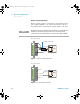
Remote Sensing
U3606B User’s Guide 121
Stability
Using remote sensing under certain combinations of load
lead lengths and large load capacitances may cause your
application to form a filter, which becomes part of the
voltage feedback loop. The extra phase shift created by this
filter can degrade the instrument stability, resulting in poor
transient response or loop instability. In severe cases, it may
cause oscillations.
To minimize this possibility, keep the load leads as short as
possible and twist them together. As the sense leads are part
of the instrument programming feedback loop, accidental
open- connections of sense or load leads during remote
sensing operation have various unwanted effects. Provide
secure and permanent connections.
CV regulation
The voltage load regulation specification in Chapter 5,
“Characteristics and Specifications,” starting on page 155
applies at the output terminals of the U3606B. When remote
sensing, add 5 mV to this specification for each 1 V drop
between the positive sensing point (S+) and output terminals
(+) due to the change in load current. Because the sense
leads are part of the U3606B feedback path, keep the
resistance of the sense leads at or below 0.5 Ω per lead to
maintain the above specified performance.
Output rating
The rated output voltage and current specifications in
Chapter 5, “Characteristics and Specifications,” starting on
page 155 apply at the output terminals of the power supply.
NOTE
If the power supply is operated with remote sensing and either the positive
or negative load wire is not connected, an internal protection circuit will
activate and shut down the power supply. To resume operation, turn the
power supply off, connect the open load wire, and turn on the power
supply.
U3606-90054_UG_EN.book Page 121 Friday, July 11, 2014 5:12 PM