Agilent U3606A Multimeter|DC Power Supply Quick Start Guide Agilent Technologies
Notices © Agilent Technologies, Inc., 2009 Warranty No part of this manual may be reproduced in any form or by any means (including electronic storage and retrieval or translation into a foreign language) without prior agreement and written consent from Agilent Technologies, Inc. as governed by United States and international copyright laws. The material contained in this document is provided “as is,” and is subject to being changed, without notice, in future editions.
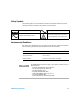
Safety Symbols The following symbols on the instrument and in the documentation indicate precautions which must be taken to maintain safe operation of the instrument. Direct current (DC) Alternating current (AC) Both direct and alternating current Caution, risk of danger (refer to this manual for specific Warning or Caution information) Environmental Conditions This instrument is designed for indoor use and in an area with low condensation.
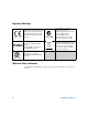
Regulatory Markings The CE mark is a registered trademark of the European Community. This CE mark shows that the product complies with all the relevant European Legal Directives. The C-tick mark is a registered trademark of the Spectrum Management Agency of Australia. This signifies compliance with the Australia EMC Framework regulations under the terms of the Radio Communication Act of 1992. ICES/NMB-001 indicates that this ISM device complies with the Canadian ICES-001.
Contents Introduction 1 The Front Panel at a Glance 2 The Display at a Glance 3 Connect the Power Cord 4 Adjust the Carrying Handle 5 Connect the Test Leads to the Terminals 6 Input terminal connections 6 Output terminal connections 7 Power-on the U3606A 8 Select a Function 9 Using the utility menu 10 Digital multimeter functions 11 DC power supply functions 17 Where to Go Next? 25 User references 25 Agilent support and contact information 25 U3606A Quick Start Guide V
VI U3606A Quick Start Guide
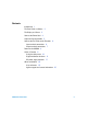
1 Introduction The Agilent U3606A Multimeter|DC Power Supply unit is a combination of a 5½ digit, 120000 count digital multimeter and a 30 W DC power supply with a square- wave generator, that is able to work simultaneously and independently. As a digital multimeter, the U3606A is capable of making DC voltage, AC voltage, AC+DC voltage, DC current, AC current, AC+DC current, 2- wire resistance, 4- wire low- resistance, capacitance, frequency, duty cycle, and pulse width measurements.
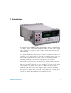
2 The Front Panel at a Glance Output terminals Input terminals Keys for digital and current fuse multimeter operation VFD display Autorange and Keys for source Shift manual range (DC power supply) or operation Local Power on/off switch For a complete list of all the keypad functions and descriptions, see Chapter 1, “Getting Started” in the U3606A User’s and Service Guide. The front panel has two rows of keys to select various functions and operations.
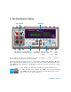
3 The Display at a Glance 6 7 8 9 11 10 1 2 3 4 5 Description 1 Primary display for digital multimeter measurements 2 Measurement functions and units 3 OUT and SBY annunciators 4 Secondary display for source operations (lower secondary display) 5 Source functions and units 6 Trigger, hold, statistics, null, diode, audible continuity, and shift annunciator 7 Source operations, Lo Ω annunciator 8 Primary display for source operations (upper secondary display) 9 Calibration and sour
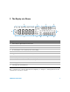
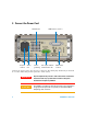
4 Connect the Power Cord Ventilation fan AC power connector AC line fuse Chassis ground lug GPIB interface connector Rear output terminals with metal short bar USB interface connector Connect the power cord to the AC power connector. The mains plug should only be inserted in a socket outlet that provides protective earth contact. 4 WA R N I N G Any interruption of the protective earth contact inside or outside the instrument makes any operation of the instrument dangerous.
5 Adjust the Carrying Handle To adjust the handle, grasp the handle by the sides and pull outward. Then, rotate the handle to the desired position. The various positions available are illustrated below.
6 Connect the Test Leads to the Terminals Input terminal connections – DC voltage, AC voltage, resistance, voltage frequency, voltage pulse width, voltage duty cycle, or capacitance measurements, and continuity or diode tests + – DC current, AC current, current frequency, current pulse width, or current duty cycle measurements up to 3 Arms + 6 U3606A Quick Start Guide
Low-resistance (Lo Ω ) 4-wire measurements Test current NOTE For low-resistance (Lo Ω ) measurements, current is sourced from the + FORCE – terminals and measured from the + SENSE – terminals.
7 Power-on the U3606A To turn on the U3606A push the power switch: The front panel display illuminates while the U3606A performs its power- on self- test. (If the U3606A does not power- on, refer to “Operating Checklist” in the U3606A User’s and Service Guide). If self- test is successful, the U3606A goes into normal operation.
8 Select a Function The U3606A Multimeter|DC Power Supply has two main features: a digital multimeter, and a DC power supply with a square- wave generator, working simultaneously and independently. • For a quick glance at measurement functions and math operations, see “Digital multimeter functions” on page 11.
Using the utility menu You can define and modify various settings in the U3606A. Modifying these settings affects the operation of your instrument across several functions. Select a setting that you want to edit to do the following: • Switch between two values, such as on or off, • Select a value from the list, or • Decrease or increase a value by using the directional keys. Key Description Press Shift > Utility to access the utility menu. Press or to step through the menu items.
Digital multimeter functions To make basic measurements, the test leads must be connected to the instrument following the input terminal connections shown in “Connect the Test Leads to the Terminals” on page 6. Most basic measurements can be made with the factory default settings. Key Description Press V to cycle between the DC, AC, and AC+DC voltage measurement functions. Press I to cycle between the DC, AC, and AC+DC current measurement functions.
Setting the range For most measurement functions, you can allow the U3606A to automatically select the range using autoranging, or you can select a fixed range using manual ranging. Key Description Press to select a higher range and disable autoranging. Press to select a lower range and disable autoranging. Press Shift > Auto to enable autoranging and disable manual ranging. Setting the resolution You can select either 4½ digit or 5½ digit resolution for most measurement functions.
Using math operations The U3606A provides six math operations: null measurements, dB measurements, dBm measurements, statistics (MinMax) for accumulated readings, limit testing, and a hold function. Key Description Press Null to enable the null math operation. Press Shift > dBm to convert the measured voltage value to dBm. Press Shift > dBm > dB to convert the measured voltage value to dB. Press MinMax to store statistical data for the current readings.
Measurement example The null function is commonly used to eliminate the effects of test leads from measurements. This example teaches you how to use the null math operation to increase the accuracy of a 2- wire resistance measurement — by nulling the test lead resistance — in the U3606A Multimeter|DC Power Supply. 1 Connect the test leads to the 2 Press (red) and LO (black) input terminals. to select the resistance function.
5 The Null annunciator will illuminate and the offset value is measured and subtracted from all resistance readings in the measurement display. Null annunciator 6 Press Null again to view and edit the offset value. 7 The offset value is displayed. Offset value 8 Use the directional keys if you wish to edit the offset value. 9 Press Shift > Save to save and exit the edit mode. (Or press Shift > Exit to exit the edit mode without saving.
10 You can now perform 2- wire resistance measurements without the effects of the test leads used. Low value resistor Test current NOTE 16 For complete instructions on all measurement functions and math operations, see Chapter 2, “Digital Multimeter Operation” in the U3606A User’s and Service Guide.
DC power supply functions The U3606A has two basic operating DC power supply modes: constant voltage (CV) and constant current (CC). Key Description Press Voltage to select CV output. Use the directional keys to select a suitable voltage value. Press Current to select CC output. Use the directional keys to select a suitable current value. Generating square waves The U3606A is capable of generating up to 4.8 kHz square waves for digital circuit troubleshooting.
Using sweep functions The U3606A comes equipped with ramp and scan capability. • When the ramp function is enabled, the Ramp annunciator will illuminate. • When the scan function is enabled, the Scan annunciator will illuminate. Key Description Press Sweep to cycle through the ramp and scan sweep functions, or to disable the sweep mode for the selected output (CV or CC).[1] [1] The sweep functions can only be accessed when the U3606A is in constant voltage or constant current mode.
Editing the scan signal properties: 1 To edit the properties of the scan signal, you will need to access the utility menu. Press Shift > Utility to access the utility menu. 2 Press or to step through the menu items until “SCAn” is shown on upper secondary display. 3 Use the directional keys to edit the signal properties. CV/CC scan signal parameters Amplitude end position (NN.NNN V or N.
Implementing protection features Protection circuits in the U3606A can limit the voltage or current to a preset level or shut down the instrument when an overvoltage or overcurrent condition occurs. The U3606A has the following protection features: • Over- voltage limit (OV) • Over- current limit (OC) • Over- voltage protection (OVP) • Over- current protection (OCP) Key Description Press Shift > Limit to set the over-current limit value for the CV output or the over-voltage limit value for the CC output.
Setting the range You can select either the S1 (30 V/1 A) or S2 (8 V/3 A) range for all output operations. The S1 range has a higher voltage range, but a lower current range. The S2 range provides a higher current range, but has a lower voltage range. The S1 or S2 annunciators will illuminate respectively when selected. Key Description Press Shift > Range select range S1 (30 V/1 A). Press Shift > Range again to select range S2 (8 V/3 A).
DC power supply example The over- voltage limit (OV) and over- voltage protection (OVP) protection features are set to the maximum by default for the constant current output. The combination of the OV and OVP protection functions create a closed loop circuit protection for sensitive load behaviors. This example teaches you how to set the OV and OVP protection values before you source a constant current from the U3606A Multimeter|DC Power Supply.
4 Press Shift > Limit to set the OV value. 5 The OV value is displayed. (Default 30 V for range S1.) 6 Use the directional keys to select a suitable OV value. 7 Press Shift > Save or Current (Limit) again to save and exit the edit mode. 8 Press Shift > Protect to set the OVP value. 9 The OVP value is displayed. (Default 33 V for range S1.
10 Use the directional keys to select a suitable OVP value. 11 Press Shift > Save or Voltage (Protect) again to save and exit the edit mode. 12 Press OUT|SBY to enable the constant current output. 13 If the load attempts to draw more voltage than required, such that it exceeds the programmed protection value, the over- voltage protection circuit will protect the load by disabling the output.
9 Where to Go Next? User references User’s and Service Guide The Agilent U3606A Multimeter|DC Power Supply User's and Service Guide contains more detailed information on the front panel, measurement functions, math operations, source operations, output functions, and the utility menu (the utility menu allows you to customize the instrument settings). It also contains information requisite to do performance tests, adjustments, troubleshooting, and repairs.
26 U3606A Quick Start Guide
www.agilent.