
Technical data

Getting Started Tutorial 1
U3402A User’s and Service Guide 25
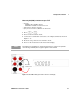
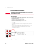
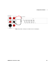
Performing diode/continuity test
Tes tin g diod es
The diode test measures the forward voltage of a semiconductor junction of
approximately 0.5 mA. The beeper will emit a single beep tone when the input
voltage is below +0.7 V (approximately 1.4 kW) and emits a continuous beep
tone when the input voltage is below 50 mV (approximately 100 W).
Measurements are displayed as shown below:
• Measurement method: 0.5 mA ± 0.2% constant current source, open-circuit voltage
limited to < +9 V
• Response time: 70 samples per seconds with audible tone
• Gate time: 0.1 s or 1 period of the input signal, whichever is longer
• Input protection: 500 V RMS on all ranges
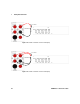
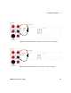
Reading rate Measurement display
Slow 1.2 V range
Medium
2.5 V range
Fast
4.0 V range
NOTE
The measurement value will display OL (overload) when the voltage measured is
• > 1.2 V at slow reading rate
• > 2.5 V at medium reading rate
• > 4.0 V at fast reading rate
CAUTION
Disconnect circuit power and discharge all high-voltage capacitors before testing
diodes to avoid damaging the multimeter.