
Technical data

4Performance Test
62 U3401A User’s and Service Guide
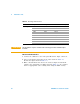
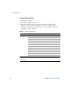
DC Current Verification Test
1 Connect the calibrator to the front panel Hi and Lo input connectors.
2 Select each function and range in the order shown in Table 4- 3.
Provide the input shown in Table 4- 3.
3 Make a measurement and observe the result. Compare measurement
results to the appropriate test limits shown in Table 4- 3. (Be certain to
allow for appropriate source settling when using the Fluke 5520A).
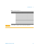
Table 4 - 2 DC voltage verification test
Function Input Range Error from nominal one year
DC voltage 0.00 V 500 mV
±40 μV
0.0000 V 5 V ±0.4 mV
0.000 V 50 V ±4 mV
0.00 V 500 V ±40 mV
0.0 V 1000 V ±400 mV
450.00 mV 500 mV
±130 μV
4.5000 V 5 V ±1.3 mV
45.000 V 50 V ±13 mV
450.00 V 500 V ±130 mV
900.0 V 1000 V ±580 mV
CAUTION
Set the calibrator output to 0 V before disconnecting it from the multimeter input
terminals.