
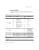
Technical data

3 Application Tutorial
52 U3401A User’s and Service Guide
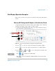
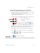
Measure AC and DC Current on a Rectification Circuit
A single measurement for both AC current and DC current can be
displayed through both displays while testing a rectifier circuit.
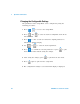
1 Connect the red and black test leads to the input terminal and probe
the test points as shown in Figure 3- 2.
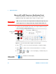
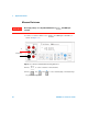
Figure 3-2 Connection terminal when using DC current and AC ripple
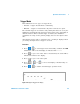
2 Press to select AC current measurement for primary display.
3 Press to enable the DC current measurement for secondary
display.
4 Press , or to select autoranging or manual range for
secondary display.
WARNING
• Make sure you select the correct input terminal according to the input range used.
• Do not apply current exceeding specified range to input terminals of mA or A.
NOTE
Press to disable the secondary display.
AC/DC current
source
+
–