Agilent U3401A 4 1/2 Digit Dual Display Multimeter User’s and Service Guide Agilent Technologies
Notices © Agilent Technologies, Inc. 2009–2013 Warranty No part of this manual may be reproduced in any form or by any means (including electronic storage and retrieval or translation into a foreign language) without prior agreement and written consent from Agilent Technologies, Inc. as governed by United States and international copyright laws. The material contained in this document is provided “as is,” and is subject to being changed, without notice, in future editions.
Safety Symbols The following symbol on the instrument and in the documentation indicates precautions that must be taken to maintain safe operation of the instrument.
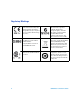
Regulatory Markings iv The CE mark shows that the product complies with all the relevant European legal Directives (if accompanied by a year, it signifies when the design was proven). The C-tick mark is a registered trademark of the Spectrum management Agency of Australia. This signifies compliance with the Australian EMC Framework regulations under the terms of the Radio Communications Act of 1992.
General Safety Information The following general safety precautions must be observed during all phases of operation, service, and repair of this instrument. Failure to comply with these precautions or with specific warnings elsewhere in this manual violates safety standards of design, manufacture, and intended use of the instrument. Agilent Technologies assumes no liability for the customer’s failure to comply with these requirements.
vi WA R N I N G • Do not defeat power cord safety ground feature. Plug in to a grounded (earthed) outlet. • Do not use multimeter in any manner that is not specified by the manufacturer. • Double-check the multimeter’s operation by measuring a known voltage. • For current measurement, turn off circuit power before connecting the multimeter to the circuit. Always place the multimeter in series with the circuit. • When connecting probes, always connect the common test probe first.
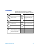
Environmental Conditions This multimeter is designed for indoor use only. The table below shows the general environmental requirements for the multimeter. NOTE Requirements Operating temperature Full accuracy from 0 °C to 50°C (Operating) Operating humidity Full accuracy up to 80 % R.H.
Waste Electrical and Electronic Equipment (WEEE) Directive 2002/96/EC This instruction complies with the WEEE Directive (2002/96/EC) marking requirement. This affixed product label indicates that you must not discard this electrical/electronic product in domestic household waste. Product Category: With reference to the equipment types in the WEEE directive Annex 1, this instrument is classified as a “Monitoring and Control Instrument” product.
Declaration of Conformity (DoC) The Declaration of Conformity (DoC) for this instrument is available on the Website. You can search the DoC by its product model or description. http://regulations.corporate.agilent.com/DoC/search.htm NOTE U3401A User’s and Service Guide If you are unable to search for the respective DoC, please contact your local Agilent representative.
In This Guide ... 1 Getting Started This chapter provides an introduction to the U3401A digital multimeter and a tutorial showing how to use the front panel in order to make masurements. 2 Operations and Features This chapter explains the various functions and features available to the U3402A digital multimeter. 3 Application Tutorial This chapter describes the advanced features and the possible applications for effective operation of the multimeter.
Contents 1 Getting Started Introducing the Agilent U3401A Dual Display Multimeter Checking the shipping contents 3 Connecting power to the instrument Stacking the U3401A 5 Adjusting the Handle 6 2 4 Product at a Glance 7 Product dimensions 7 The front panel at a glance 8 The display at a glance 9 The rear panel at a glance 16 Making measurements 17 Performing voltage measurements 18 Performing current measurements 20 Performing frequency measurements 22 Performing resistance/continuity measurements P
Using the Secondary Display 41 Using the Setup Menu 43 Changing the Configurable Settings Trigger Mode 45 3 44 Application Tutorial Applications for Using Dual Display 50 Dual Display Operation Examples 51 Measure DC Voltage and AC Ripple on a Rectification Circuit 51 Measure AC and DC Current on a Rectification Circuit 52 Measure AC Voltage and Frequency on an AC Circuit 53 Measure Resistance 54 Measure True RMS AC + DC 55 4 Performance Test Calibration Overview 58 Agilent Technologies Calibration S
To Replace a Current Input Fuse 74 Electrostatic Discharge (ESD) Precautions Mechanical Disassembly 75 Replaceable Parts 81 To order replaceable parts 6 74 81 Specifications and Characteristics DC Specifications 84 AC Specifications 85 True RMS AC Voltage True RMS AC Current Frequency 87 85 86 Decibel (dB) Calculation 88 Supplemental Measurement Specifications Display update rate 89 Measurement Specifications 89 Reading rates 96 General Characteristics 89 97 To Calculate Total Measurement Err
xiv U1253B User’s and Service Guide
List of Figures Figure 1-1 Figure 1-2 Figure 1-3 Figure 1-4 Figure 1-5 Figure 1-6 Figure 1-7 Figure 1-8 Figure 1-9 Figure 1-10 Figure 1-11 Figure 1-12 Figure 1-13 Figure 1-14 Figure 1-15 Figure 1-16 Figure 1-17 Figure 2-1 Figure 2-2 Figure 2-3 Figure 2-4 Figure 2-5 Figure 2-6 Figure 2-7 Figure 2-8 Figure 2-9 Figure 2-10 Figure 3-1 Figure 3-2 U1253B User’s and Service Guide Stacking the U3401A 5 Type of handle position 6 Attaching and detaching the handle 6 U3401A dimensions 7 Front panel 8 VFD full displa
Figure 3-3 Connection terminal when measuring AC Voltage and Frequency 53 Figure 3-4 Connection terminal when measuring Resistance 54 xvi U1253B User’s and Service Guide
List of Tables Table 1-1 Table 1-2 Table 1-3 Table 1-4 Table 2-1 Table 2-2 Table 2-3 Table 3-1 Table 4-1 Table 4-2 Table 4-3 Table 4-4 Table 4-5 Table 4-6 Table 4-7 Table 4-8 Table 5-1 Table 5-2 Table 6-1 Table 6-2 Table 6-3 Table 6-4 Table 6-5 Table 6-6 Table 6-7 Table 6-8 Table 6-9 Table 6-10 Table 6-11 U1253B User’s and Service Guide Display annunciators 9 Keypad functions 11 Input terminal for different functions 15 Range scale value 27 Math operations for different measurement functions 30 Descriptio
xviii U1253B User’s and Service Guide
U3401A 4 ½ Digit Dual Display Multimeter User’s and Service Guide 1 Getting Started Introducing the Agilent U3401A Dual Display Multimeter 2 Checking the shipping contents 3 Connecting power to the instrument 4 Stacking the U3401A 5 Adjusting the Handle 6 Product at a Glance 7 Product dimensions 7 The front panel at a glance 8 The display at a glance 9 The keypad at a glance 11 The terminals at a glance 14 The rear panel at a glance 16 Making measurements 17 Performing voltage measurements 18 Performing cu
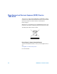
1 Getting Started Introducing the Agilent U3401A Dual Display Multimeter The key features of the U3401A dual display multimeter are: • 4 ½- digit dual display measurement • Ten measurement functions: • AC voltage • DC voltage • AC current • DC current • AC + DC voltage • AC + DC current • Resistance • Frequency • Continuity test • Diode test • Six math operations: • dBm • Min/Max • Hold • Relative (Rel) • Compare (Comp) • Percentage (%) • 50,000 count dual display.
Getting Started 1 Checking the shipping contents Verify that you have received the following items with your multimeter: • Power cord • Standard test lead kit • Quick start guide • Product reference CD • Test report • Certificate of calibration Inspect the shipping container for damage. Signs of damage may include a dented or torn shipping container or cushioning material that shows signs of unusual stress or compacting.
1 Getting Started Connecting power to the instrument Connect the power cord and press the power switch to turn on the multimeter. The front panel display illuminates while the multimeter performs its power- on self- test. (If the multimeter does not power- on, refer “Operating Checklist” on page 70). During the power- on session, press to hold the full display. Press any key to resume the power- on self- test. The multimeter powers up in the DC voltage function with autoranging enabled.
Getting Started 1 Stacking the U3401A The U3401A is shipped with specially designed anti- slip protective bumpers on the front and rear panel. The multimeters will not slide off when stacked on top of each other. To be able to stack the U3401A multimeters, ensure the attached bumpers are in correct orientation. See Figure 1- 1.
1 Getting Started Adjusting the Handle To adjust the handle, grasp the handle by the side and pull outward. Then, rotate the handle to the desired position. Figure 1- 2 below shows the possible handle positions. Carrying position Benchtop position Handle removal position Figure 1-2 Type of handle position To attach or detach the handle, rotate the handle upright and pull it out from the sides of the multimeter. Refer to Figure 1- 3.
Getting Started 1 Product at a Glance Product dimensions Front view 226.0 mm Side view 105.0 mm 305.
1 Getting Started The front panel at a glance Primary display Input terminals and current fuse Measurement function keypads Secondary display Autoranging, manual range, and comparator operation Shift Power Math on/off operation switch keypads Figure 1-5 Front panel 8 U3401A User’s and Service Guide
Getting Started 1 The display at a glance Figure 1-6 VFD full display with all segments illuminated The highly visible vacuum fluorescent display (VFD) annunciators are described in Table 1- 1. Table 1-1 Display annunciators Annunciator Primary display S M F PEAK HOLD MIN MAX REL dBm 42W AUTO DC AC DCAC U3401A User’s and Service Guide Description Reading rate: Slow. Not applicable for the U3401A. Reading rate: Medium. Not applicable for the U3401A. Reading rate: Fast. Not applicable for the U3401A.
1 Getting Started Annunciator Description Polarity, digits, and decimal points for primary display °C °F mV μmA μmnF MkΩ MkHz Secondary display Celcius temperature unit. Not applicable for the U3401A. Fahrenheit temperature unit. Not applicable for the U3401A.
Getting Started 1 The keypad at a glance The operation for each key is shown on Table 1- 2. Pressing a key changes the current key operation, illuminates the related symbol on the display and emits a beep. Figure 1-7 Keypad Table 1-2 Keypad functions Key Description System related operation Press to power-on or power-off the U3401A multimeter. Press to select Shift. Press to return the multimeter to front panel operation when it is in remote state. + Press to step through the Setup menu.
1 Getting Started Table 1-2 Keypad functions Key Description Measurement related operation Press to disable the secondary display. + Press to select the DC voltage measurement. Press to select the AC voltage measurement. Press to select the DC current measurement. Press to select the AC current measurement. Press to select the AC + DC voltage measurement. + Press to select AC + DC current measurement. + Press to select the frequency measurement.
Getting Started 1 Table 1-2 Keypad functions Key Description Measurement related operation Press to select a lower range and disable autoranigng. See “Selecting a Range” on page 26 for more information. Press to select Compare math operation. + Press to select and set the high limit for Compare math operation. + Press to select and set the low limit for Compare math operation. + Press to enable Hold math operation. See “Hold” on page 37 on for more information.
1 Getting Started The terminals at a glance CAUTION To avoid damaging this multimeter, do not exceed the rated input limit. Figure 1-8 Input terminals NOTE 14 Voltages above 300 VAC may be measured only in circuits that are isolated from mains. However, transient overvoltages are also present on circuits that are isolated from mains. The Agilent U3401A is designed to safely withstand occasional transient overvoltages up to 2500 V PEAK.
Getting Started 1 Table 1-3 Input terminal for different functions Measurement function Input terminal DC voltage (VDC) Overload protection 1000 VDC 750 VAC RMS, 1100 V PEAK, 2x10⁷ V-Hz normal mode, or AC voltage (VAC), frequency (Hz) 1x10⁶ V-Hz common mode Miliampere (mA), frequency (Hz) mA 500 mADC or AC RMS COM 10 A, frequency (Hz) 10 A 10 ADC or AC RMS continuous, and >10 A DC RMS for 20 seconds maximum Resistance (Ω) 500 VDC or AC RMS Diode test, continuity test 500 VDC or AC RMS All f
1 Getting Started The rear panel at a glance Line voltage fuse AC line voltage selector selection table AC power connector AC line fuse Chassis ground lug RS232 interface connector (For calibration use only) Figure 1-9 Rear panel 16 U3401A User’s and Service Guide
Getting Started 1 Making measurements The following pages show you how to make measurement connections and how to select measurement functions from the front panel for each of the measurement functions.
1 Getting Started Performing voltage measurements CAUTION Ensure that the terminal connections are connected correctly before making any measurement. To avoid damaging the multimeter, do not exceed the rated input limit. AC voltage • Five ranges: 500.00 mV, 5.00 V, 50.00 V, 500.00 V, 750.
Getting Started 1 DC Voltage • • • • Five ranges: 500.00 mV, 5.00 V, 50.00 V, 500.00 V, 1000.00 V Measurement method: Sigma Delta A-to-D converter Input impedance: 10 MΩ±2% range (typical) Input protection: 1000 V on all ranges 1 Press . 2 Connect the red and black test leads to the respective input terminals as shown in Figure 1- 11. 3 Probe the test points and read the display. In autoranging mode, the multimeter automatically selects the appropriate range and the measurement is displayed.
1 Getting Started Performing current measurements Measuring AC (RMS) or DC Current in mA • Measurement ranges: 500.00 μA, 5.00 mA, 50.00 mA, 500.00 mA • Shunt resistance: 0.01 W to 100 W for 500 μA to 10 A ranges • Input protection: Internal 25 A, 440 V FH fuse for one terminal 1 Press or . 2 Power off the measured circuit. 3 Connect the red and black test leads to mA input terminal as shown in Figure 1- 12. 4 Probe the test points in series with the circuit.
Getting Started 1 Measuring AC (RMS) or DC Current up to 10 A • Measurement ranges: • 5.000 A, 10.000 A for DC or AC RMS continuous • 12.000 A DC or AC RMS for maximum 30 seconds • Shunt resistance: 0.01 W to 100 Ω for 500 μA to 10 A ranges • Input protection: Internal 25 A, 440 V fuse for 10A terminal, 1 Press or 2 Press or . to select the measurement range. 3 Power off the measured circuit. 4 Connect the red and black test leads to the A input terminal as shown in Figure 1- 13.
1 Getting Started Performing frequency measurements WA R N I N G Use the frequency counter for low voltage applications. Do not use the frequency counter on AC power line systems. • Five ranges: • 500.00 mV, 5.0000 V, 50.000 V, 500.000 V, 750.000 V • Range is based on the voltage level of the signal, not frequency • Measurement method: Reciprocal counting technique. AC coupled input using AC voltage function • Signal level: 10% of range to full scale input on all ranges • Gate time: 0.
Getting Started 1 Performing resistance/continuity measurements CAUTION Disconnect circuit power and discharge all high-voltage capacitors before measuring resistance, or testing circuit continuity, to avoid damaging the multimeter or the device under test. • Six ranges: 500.00 W, 5.0000 kW, 50.000 kW, 500.00 kW, 5.000 MW,, 50.000 MW, • Measurement method: Two-wire ohms, open circuit voltage limited to <5 V • Input protection: 500 V on all ranges 1 Press .
1 Getting Started Performing diode and continuity Test The diode test measures the forward voltage of a semiconductor junction of approximately 0.5 mA. The beeper will emit a single beep tone when the input voltage is below +0.7 V (approximately 1.4 kW) and emits a continuos beep tone when the input voltage is below 50 mV (approximately 100 W). CAUTION Disconnect circuit power and discharge all high-voltage capacitors before testing diodes to avoid damaging the multimeter. • Measurement method: 0.
Getting Started 1 • A diode is considered shorted if the multimeter displays approximately 0 V in both forward and reverse bias modes, and the multimeter beeps continuously. • A diode is considered open if the multimeter displays OL in both forward and reverse bias modes.
1 Getting Started Selecting a Range You can allow the multimeter to select the range automatically by using autoranging, or you can select a fixed range using manual ranging. Autoranging is convenient because the multimeter automatically selects the appropriate range for sensing and displaying each measurement. However, manual ranging results in better performance, since multimeter does not have to determine which range to use for each measurement. Selects autoranging and disable manual ranging.
Getting Started 1 Table 1-4 Range scale value Measurement function DCV Range 500.000 mV, 5.000 V, 50.000 V, 500.000 V, 1000.00 V ACV , DCV + ACV 500.000 mV, 5.000 V, 50.000 V, 500.000 V, 750.000 V DCI , ACI , DCI + ACI 500.000 μA, 5.000 mA, 50.000 mA, 500.000 mA DCI, ACI , DCI + ACI 5.000 A, 10.000 A Frequency 500.000 Hz, 5.000 kHz, 500.000 kHz, 500.000 kHz Resistance 500.000 Ω, 5.000 kΩ, 50.000 kΩ, 500.000 kΩ, 5.000 MΩ, 50.000 MW Diode test 2.3000 V Continuity 500.000, 5.000 k, 50.
1 28 Getting Started U3401A User’s and Service Guide
U3401A 4 ½ Digit Dual Display Multimeter User’s and Service Guide 2 Operations and Features Operating Math Functions 30 dBm 31 Rel 32 MinMax 33 Comp 35 Hold 37 Percentage (%) 39 Using the Secondary Display 41 Using the Setup Menu 43 Changing the Configurable Settings 44 This chapter explains the various functions and features available on the U3401A digital multimeter.
2 Operations and Features Operating Math Functions Table 2- 1 presents a summary of the math operations that can be used with each measurement function. Table 2-1 Math operations for different measurement functions Measurement Function DCV DCI Resistance ACV ACI Frequency Diode/Continuity dBm Rel — — — — — — — Allowed math operations Min Max Comp Hold % • All math operations can be toggled on and off by selecting the same math operation. • Only one math operation can be turned- on at a time.
Operations and Features 2 dBm The logarithmic dBm (decibels relative to one milliwatt) scale is often used in RF signal measurements. The multimeter’s dBm operation takes a measurement and calculates the power delivered to a reference impedance (typically 50, 75 or 600 Ω). The formula used for conversion from the voltage reading is: dBm = 10 x Log10 [1000 x (Reading2 / reference impedance)] Figure 2-1 Typical dBm operation display The default reference impedance value is 600 Ω..
2 Operations and Features Rel When making Rel (relative) measurements, each reading is the difference between a stored relative value and the input signal. For example, this feature can be used to make more accurate resistance measurements by nulling the test lead resistance.
Operations and Features 2 MinMax The MinMax (Minimum/Maximum) operation stores the minimum and maximum values of reading during a series of measurements. When enabled, the MinMax operation turns on the MINMAX annunciator and begins accumulating various statistics of the readings being displayed.
2 Operations and Features The elapsed time is recorded when the MinMax operation is selected. The elapsed time is shown on the secondary display with HH.MM.SS. • HH is 0- 19 hours • MM is 0- 59 minutes • SS is 0- 59 seconds Procedure 1 Press to enable MinMax operation. 2 Press continuously until the desired operation appear. The MinMax operation will display MINMAX > MAX > MIN > MINMAX in sequence when this key is press continuously. 3 Press 34 to disable the MinMax operation.
Operations and Features 2 Comp The Comp (compare) operation allows you to perform pass/fail testing against specified upper and lower limits. You can set the upper and lower limits to any value between 0 and ±100% of the highest range for the present operation. Figure 2-5 Typical Comp operation display When enabled, the actual readings are shown in primary display and the comparison results such as HI, LO or PASS is shown in secondary display.
2 Operations and Features Procedure 1 Press to enter the upper limit setup mode. The upper limit is shown on primary display while the HI annunciator is shown on secondary display. 2 Use , 3 Press , , and to modify the upper limit. to store the specified HI limit value. 4 Press to enter the lower limit setup mode. The lower limit is shown on primary display while the LO annunciator is shown on secondary display. 5 Use 6 Press 36 , , , and to modify the lower limit.
Operations and Features 2 Hold The reading hold feature allows you to capture and hold a reading on the front panel display. When enabled, the Hold operation turns on the HOLD annunciator and hold the reading. Procedure 1 Press to hold the reading on the display. Figure 2-6 Typical Hold operation display Refresh Hold The refresh hold operation allows you to take measurement in dangerous or difficult measuring field and you could not look at the display.
2 Operations and Features 5 Press twice quit the Setup menu. 6 Press to select refresh hold mode. The present value will be held and the HOLD will be lit. The multimeter is now ready to hold a new measurement value once the variation of measuring value exceeds the setting of the variation count. The HOLD annunciator will be blinking continuously. 7 When the refresh hold is not in use, repeat step 1 to step 4 to turn off the refresh hold’s state.
Operations and Features 2 Percentage (%) This operation allows you to transfer the measurement value with a proportional percentage display. You can set the upper limit (HI) and lower limit (LO) to any value between 0 and ±100% of the highest range for the present function.
2 Operations and Features Procedure 1 Press to enter the upper limit setup mode. The upper limit is shown on primary display while the HI annunciator is shown on secondary display. 2 Use , 3 Press , , and to modify the upper limit. to store the specified HI limit value. 4 Press to enter the lower limit setup mode. The lower limit is shown on primary display while the LO annunciator is shown on secondary display. 5 Use 40 , , , and to modify the lower limit.
Operations and Features 2 Using the Secondary Display Secondary display Figure 2-9 Secondary display To enable the secondary display mode: Repeatedly pressing cycles through the secondary display choices for the present math operation as shown in Table 2- 2 on page 42. To disable the secondary display mode: Press U3401A User’s and Service Guide . The display will remain in primary display mode.
2 Operations and Features Table 2-2 Description for dual display combination Secondary Display Primary Display DCV Default secondary display Frequency Press secondary display once Press secondary display twice ACV [2] dBm Press secondary display three times — ACV ACV + DCV Frequency DCV [2] dBm — Frequency ACV [2] DCV [2] dBm dBm ACV DVC ACV+DCV — DCI Frequency ACI [2] — — ACI Frequency DCI [2] — — ACI + DCI Frequency ACI [2] DCI[2] — Frequency [1] ACV ACI — — COM
Operations and Features 2 Using the Setup Menu The Setup menu allows you to customize a number of non- volatile instrument configurations. The content of the Setup menu are shown in Table 2- 3. .
2 Operations and Features Changing the Configurable Settings The parameters in the Setup Menu can be configured by using the following procedures: 1 Press 2 Press to access to the Setup Menu. and to select the desired configurable items in the first tier menu. 3 Press to enter second tier menu. The original parameter is indicated in primary display. 4 Use 5 Press or to select the desired parameter.
Operations and Features 2 Trigger Mode This multimeter has two types of trigger mode. • Internal — triggers measurements continuously. • External — triggers a measurement only when a direction is given. The external trigger is used with a delay settling that has been set by the multimeter automatically. The amount of trigger delay varies depending on different function. When external trigger is enabled, the multimeter determines the range for the primary display based on the input at that time.
2 Operations and Features NOTE • All math operations will be disabled when external trigger is enabled. • Press may also disable external trigger. • Both the primary and secondary display will only appear when frequency operation is selected in trigger mode.
U3401A 4 ½ Digit Dual Display Multimeter User’s and Service Guide 3 Application Tutorial Applications for Using Dual Display 50 Dual Display Operation Examples 51 Measure DC Voltage and AC Ripple on a Rectification Circuit 51 Measure AC and DC Current on a Rectification Circuit 52 Measure AC Voltage and Frequency on an AC Circuit 53 Measure Resistance 54 Measure True RMS AC + DC 55 This chapter describes the advanced features and the possible applications for effective operation of the multimeter.
3 Application Tutorial Applications for Using Dual Display The dual display feature in the multimeter can be used to enhance test and measurement capabilities. See Table 3- 1 for the available combinations and application when using dual display. Table 3-1 Typical combinations and applications when using dual display 50 No. Primary display Secondary display 1 DCV ACV Applications • Test DC to AC or AC to DC converter circuit. • Measure DC level and AC ripple of power supply.
Application Tutorial 3 Dual Display Operation Examples This section describes some practical operations when using dual display feature. Measure DC Voltage and AC Ripple on a Rectification Circuit A single measurement for both DC voltage and AC ripple can be displayed through both displays while testing a rectifier circuit. 1 Connect the red and black test leads to the input terminal and probe the test points as shown in Figure 3- 1.
3 Application Tutorial Measure AC and DC Current on a Rectification Circuit A single measurement for both AC current and DC current can be displayed through both displays while testing a rectifier circuit. • Make sure you select the correct input terminal according to the input range used. WA R N I N G • Do not apply current exceeding specified range to input terminals of mA or A. 1 Connect the red and black test leads to the input terminal and probe the test points as shown in Figure 3- 2.
Application Tutorial 3 Measure AC Voltage and Frequency on an AC Circuit A single measurement for both AC voltage and frequency can be displayed through both displays while testing a rectifier circuit. 1 Connect the red and black test leads to the input terminal and probe the test points as shown in Figure 3- 3. + AC voltage source – Figure 3-3 Connection terminal when measuring AC Voltage and Frequency 2 Press to select AC voltage measurement for primary display.
3 Application Tutorial Measure Resistance WA R N I N G Do not apply voltage exceeding 500 V PEAK between terminals. 1 Connect a resistor under test to shown in Figure 3- 4. and COM input and LO input terminals as + Resistance – Figure 3-4 Connection terminal when measuring Resistance 2 Press 3 Press to select resistance measurement. . Use and to select autoranging or manual range for primary display.
Application Tutorial 3 Measure True RMS AC + DC The multimeter can measure the true RMS of AC voltage and AC current. 1 Press , and or and simultaneously. The multimeter will measure the DC and AC signals alternatively, calculate and display the AC+DC RMS value using the quation below: AC+DC (RMS) = NOTE DC2 + AC2 When AC+DC voltage measurement is selected, the DCV input impedance is paralleled with the AC coupled 1.1 MΩ AC divider.
3 56 Application Tutorial U3401A User’s and Service Guide
U3401A 4 ½ Digit Dual Display Multimeter User’s and Service Guide 4 Performance Test Calibration Overview 58 Agilent Technologies Calibration Services 58 Calibration Interval 58 Recommended Test Equipment 59 Test Considerations 60 Performance Verification Tests Overview 61 Performance Verification Tests 61 DC Voltage Verification Test 61 DC Current Verification Test 62 Resistance Verification Test 64 Diode Verification Test 65 Frequency Verification Test 65 AC Voltage Verification Test 66 AC Current Verifi
4 Performance Test Calibration Overview NOTE Make sure you have read “Test Considerations” on page 60 before calibrating the instrument. Agilent Technologies Calibration Services When your instrument is due for calibration, contact your local Agilent Service Center. The U3401A is supported on automated calibration systems at Agilent service centres only. Calibration Interval A one- year interval is adequate for most applications.
Performance Test 4 Recommended Test Equipment The test equipments recommended for the performance verification procedures are listed below. If the exact instrument is not available, substitute calibration standards of equivalent accuracy. A suggested alternate method would be to use the Agilent 3458A 8½ - digit digital multimeter to measure less accurate yet stable sources. The output value measured from the source can be entered into the instrument as the target calibration value.
4 Performance Test Test Considerations For optimum performance, all procedures should comply with the following recommendations: • Ensure that the calibration ambient temperature is stable and between 18°C and 28°C. Ideally the calibration should be performed at 23°C ±1°C. • Ensure ambient relative humidity is less than 80%. • Allow a 30 minutes warm- up period with a Shorting Plug connected to the Hi and Lo input terminals.
Performance Test 4 Performance Verification Tests Overview Performance verification tests is an extensive set of tests that are recommended as an acceptance test when you first receive the instrument. Use the performance verification test to verify the measurement performance of the instrument.
4 Performance Test Table 4-2 DC voltage verification test CAUTION Function Input Range Error from nominal one year DC voltage 0.00 V 500 mV ±40 μV 0.0000 V 5V ±0.4 mV 0.000 V 50 V ±4 mV 0.00 V 500 V ±40 mV 0.0 V 1000 V ±400 mV 450.00 mV 500 mV ±130 μV 4.5000 V 5V ±1.3 mV 45.000 V 50 V ±13 mV 450.00 V 500 V ±130 mV 900.0 V 1000 V ±580 mV Set the calibrator output to 0 V before disconnecting it from the multimeter input terminals.
Performance Test 4 Table 4-3 DC current verification test CAUTION Function Input Range Error from nominal one year DC current 0.00 μA 500 μA ±0.05 μA 0.0000 mA 5 mA ±0.4 μA 0.000 mA 50 mA ±4 μA 0.00 mA 500 mA ±40 μA 450.00 μA 500 μA ±0.27 μA 4.5000 mA 5 mA ±2.6 μA 45.000 mA 50 mA ±26 μA 450.00 mA 500 mA ±0.26 mA 0.0000 A 5A ±0.5 mA 0.000 A 10 A ±5 mA 4.5000 A 5A ±11.7 mA 9.
4 Performance Test Resistance Verification Test Configuration: 2- Wire Ω 1 Select the resistance function. 2 Select each range in the order shown in Table 4- 4. Provide the resistance value indicated. Compare measurement results to the appropriate test limits shown in Table 4- 4. (Be certain to allow for appropriate source settling). Table 4-4 2-wire Ω verification test Function Input Range Error from nominal one year 2-wire Ω 0.00 Ω 500 Ω ±50 mΩ[1] 0.0000 kΩ 5 kΩ ±0.3 Ω[1] 0.
Performance Test 4 Diode Verification Test Configuration: Diode 1 Connect the calibrator to the front panel Hi and Lo input terminals. 2 Select each function and range in the order shown in Table 4- 5. Provide the input shown in Table 4- 5. 3 Make a measurement and observe the result. Compare measurement results to the appropriate test limits shown in Table 4- 5. (Be certain to allow for appropriate source settling when using the Fluke 5520A).
4 Performance Test AC Voltage Verification Test Configuration: AC volts 1 Select the AC voltage function. 2 Select each range in the order shown in Table 4- 7. Provide the indicated input voltage and frequency. Compare measurement results to the appropriate test limits shown in Table 4- 7. (Be certain to allow for appropriate source settling). Table 4-7 AC volts verification test CAUTION 66 Error from nomial one year Function V RMS Input frequency Range AC voltage 50.
Performance Test 4 AC Current Verification Test Configuration: AC current 1 Select the AC current function. 2 Select each range in the order shown in Table 4- 8. Provide the input current and frequency indicated. Compare measurement results to the appropriate test limits shown in Table 4- 8. (Be certain to allow for appropriate source settling). Table 4-8 AC current verification test Input frequency Range Error from nominal one year 50.00 μA 1 kHz 500 μA ±0.45 μA 450.00 μA 1 kHz 500 μA ±2.
4 68 Performance Test U3401A User’s and Service Guide
U3401A 4 ½ Digit Dual Display Multimeter User’s and Service Guide 5 Disassembly and Repair Operating Checklist 70 Types of Service Available 71 Repackaging for Shipment 72 Cleaning 72 To Replace the Power Line Fuse 73 To Replace a Current Input Fuse 74 Electrostatic Discharge (ESD) Precautions 74 Mechanical Disassembly 75 Replaceable Parts 81 This chapter will help you troubleshoot a faulty multimeter.
5 Disassembly and Repair Operating Checklist Before returning your multimeter to Agilent for service or repair check the following items: Is the multimeter inoperative? q Verify the power line voltage setting. q Verify the power line fuse is installed. q Check the power cord is connected to multimeter and to AC line power. q Verify the front panel power switch is depressed. See page 72 Is the mutimeter’s current input inoperative? q Verify the current input fuse.
Disassembly and Repair 5 Types of Service Available If your instrument fails during the warranty period, Agilent Technologies will repair or replace it under the terms of your warranty. After your warranty expires, Agilent offers repair services at competitive prices. Extended Service Contracts Many Agilent products are available with optional service contracts that extend the covered period after the standard warranty expires.
5 Disassembly and Repair Repackaging for Shipment If the instrument is to be shipped to Agilent for service or repair, be sure to: • Attach a tag to the unit identifying the owner and indicating the required service or repair. Include the model number and full serial number. • Place the unit in its original container with appropriate packaging material for shipping. • Secure the container with strong tape or metal bands.
Disassembly and Repair 5 To Replace the Power Line Fuse The power line fuse is located within the multimeter’s fuse- holder assembly on the rear panel. The multimeter is shipped from the factory with a power- line fuse installed (according to country of destination). See Table 5- 1. If you determine that the fuse is faulty, replace it with one of the same size and rating. Table 5-1 Type of supplied fuse (according to country of destination) Type of fuse (time-lag, low breaking fuse) 0.
5 Disassembly and Repair To Replace a Current Input Fuse Both the mA and the A current input terminals are fuse protected. The fuse for the mA input terminal is located on the front panel (see page 15). The fuse is a 0.63 mA, 500 V fuse (refer to Table 5- 2). If you determine that the fuse is faulty, replace it with one of the same size and rating. The fuse for the A current input terminal is located inside the multimeter (see page 79) and requires partial disasembly of the multimeter.
Disassembly and Repair 5 Mechanical Disassembly For procedures in this manual, the following tools are required for disassembly: • T15 Torx driver • T20 Torx driver (most disassembly) • #2 Pozi- drive screw driver WA R N I N G Shock hazard. Only service–trained personnel who are aware of the hazards involved should remove the instrument covers. To avoid electrical shock and personal injury, make sure to disconnect the power cord from the instrument before removing the covers.
5 Disassembly and Repair 3 Remove the instrument bumpers. Pull from a corner and stretch the bumpers off the instrument. 4 Remove the rear bezel. Loosen the two captive screws in the rear bezel and remove the rear bezel.
Disassembly and Repair 5 5 Remove the cover. Remove the screw in the bottom of the cover and slide the cover off the instrument. Front Panel Removal 1 Remove on/off switch push rod. Gently move the power switch push rod toward the front of the instrument to disengage it from the switch. Be careful not to twist or bend the push rod.
5 Disassembly and Repair 2 Remove the screw holding the front panel. 3 Disconnect the two ribbon cable connectors from the front panel.
Disassembly and Repair 5 4 Disconnect the individual front panel wires shown below. 25 A current fuse 5 There is now enough play to allow the side of the front panel to be pried from the chassis and removed as an assembly.
5 Disassembly and Repair Front Panel Disassembly 1 Remove the keyboard and display assembly. Remove the two screws holding the circuit board. Lift the keyboard and display assembly from the plastic housing. a The rubber keypad can now be pulled from the plastic housing.
Disassembly and Repair 5 Replaceable Parts This section contains information for ordering replacement parts for your instrument. You can find the instrument support part list at Agilent’s Test & Measurement Parts Catalog at http://www.agilent.com/find/parts This parts list includes a brief description of each part with applicable Agilent part number. To order replaceable parts You can order replaceable parts from Agilent using the Agilent part number.
5 82 Disassembly and Repair U3401A User’s and Service Guide
U3401A 4 ½ Digit Dual Display Multimeter User’s and Service Guide 6 Specifications and Characteristics DC Specifications 84 AC Specifications 85 True RMS AC Voltage 85 True RMS AC Current 86 Frequency 87 Decibel (dB) Calculation 88 Supplemental Measurement Specifications 89 Display update rate 89 Measurement Specifications 89 Reading rates 96 General Characteristics 97 To Calculate Total Measurement Error 99 Accuracy Specifications 100 This chapter describes the multimeter’s specifications and operating c
6 Specifications and Characteristics DC Specifications Table 6-1 DCV resolution, full scale reading and accuracy [±(% of reading + count)] Function Voltage Current Maximum reading Accuracy Typical input Burden voltage (One year; 23°C ± Test Current [3] impedance [2] 5 °C) 0.02% + 4 — 10.0 MΩ — 0.02% + 4 — 11.1 MΩ — 0.02% + 4 — 10.1 MΩ — 0.02% + 4 — 10.0 MΩ — Range Resolution 500 mV 5V 50 V 500 V 0.01 mV 0.0001 V 0.001 V 0.01 V 510.00 5.1000 51.000 510.00 1000 V 0.1 V 1200.0 [1] 0.
Specifications and Characteristics 6 AC Specifications True RMS AC Voltage Table 6-2 ACV resolution and full scale reading [±(% of reading + count)] Mode AC coupling AC + DC coupling Accuracy (One year; 23°C ± 5°C) [2] 50 Hz to 10 10 kHz to 30 30 kHz to 100 30 Hz to 50 Hz kHz kHz kHz 1% + 40 0.5% + 40 2% + 60 3% + 120 Resolution Maximum reading 500 mV 0.01 mV 510.00 5V 0.0001 V 5.1000 1% + 20 0.35% + 15 1% + 20 3% + 50 50 V 0.001 V 51.000 1% + 20 0.
6 Specifications and Characteristics True RMS AC Current Table 6-3 ACI resolution, full scale reading, and burden voltage [±(% of reading + count)] Mode AC Accuracy (One year; 23°C ± 5°C) [5] Maximum 2 kHz to 5 5 kHz to 20 reading 30 Hz to 50 50 Hz to 2 Hz kHz kHz kHz Range Resolution 500 μA 0.01 μA 510.00 5 mA 0.0001 mA 5.1000 1.5% + 40 0.5% + 20 50 mA 0.001 mA 51.000 1.5% + 40 0.5% + 20 500 mA 0.01 A 510.00 1.5% + 40 5A 0.0001 A 5.1000 2% + 40 [3] 10 A 0.001 A 20.
Specifications and Characteristics 6 Frequency Table 6-4 Frequency resolution and accuracy [± (% of reading + count)] Range Measurement range Resolution Maximum reading Accuracy (One year; 23°C ± 5°C) 0.01% + 5 500 Hz 5 Hz to 500 Hz 0.01 Hz 510.00 5 kHz 500 Hz to 5 kHz 0.0001 kHz 5.1000 50 kHz 5 kHz to 50 kHz 0.001 kHz 51.000 0.01% + 3 500 kHz 50 kHz to 500 kHz 0.01 kHz 999.99 0.01 %+ 3 0.
6 Specifications and Characteristics Decibel (dB) Calculation Table 6-7 Range and accuracy (dB) 500 mV 5V 50 V 500 V 20 mV to 500 m V 500 mV to 5 V 5 V to 50 V dBm [3] range at 600 Ω ref –29.82 to –3.80 –3.80 to 16.20 16.20 to 36.20 50 V to 500 V 36.20 to 56.20 1000 V (dc) 500 V to 1000 V 56.20 to 62.22 Voltage range [1][2] Input voltage Accuracy(One year; 23°C ± 5°C) (dB) 30 Hz to 50 Hz 50 Hz to 10 kHz 10 kHz to 100 kHz 0.3 0.3 0.7 0.2 0.2 0.5 0.2 0.2 0.5 0.2 [5] — 500 V to 750 V 56.20 to 59.
Specifications and Characteristics 6 Supplemental Measurement Specifications Display update rate Table 6-8 Full scale display update rate Display Count 50000 Measurement Specifications Table 6-9 Measurement specifications DC voltage • Measurement method • Sigma Delta A-to-D converter • Input resistance • 10 MΩ ± range (typical) • Maximum input voltage • 1000 VDC or PEAK AC on all ranges • Input protection • 1000 V on all ranges • Response time • Approximate 1.
6 Specifications and Characteristics Table 6-9 Measurement specifications (continued) DC current • Shunt resistance • 0.01 W to 100 W for 500 μA to 10 A ranges • Response time • Approximate 1.0 second when the displayed reading reaches 99.9% DC value of the tested input signal at the same range.
Specifications and Characteristics 6 Table 6-9 Measurement specifications (continued) AC voltage (True RMS AC + DC Coupling Mode) • Measurement method • AC+DC coupled true RMS — measure the AC component with up to 400 VDC bias on any range • Crest factor • Maximum 3:0 at full scale • Input impedance • 1 MΩ in parallel with <100 pF • Maximum input voltage • 1000 V RMS / 1400 V PEAK • 2x10⁷ V-Hz product on any range, common mode input • 1x10⁶ V-Hz product on any range, normal mode input • Overload ranging •
6 Specifications and Characteristics Table 6-9 Measurement specifications (continued) AC current (True RMS, AC Coupling Mode) • Measurement method • DC coupled to the fuse and current shunt, AC coupled true RMS measurement (measures the AC component only) • Crest factor • Maximum 3:0 at full scale • Shunt resistance • 0.01 Ω to 100 Ω for 500 μA to 10 A ranges • Input protection • Front panel fuse 630 mA, 500 V, Internal 25 A, 440 V • Response time • Approximate 1.
Specifications and Characteristics 6 Table 6-9 Measurement specifications (continued) Resistance • Measurement method • 2-wire Ohms • Open-circuit voltage • Limited to +6.0 VDC • Zeroing error • 0.05 Ω or less (excluding test lead resistances) in each range when Rel operation is used • Input protection • 500 V DC or AC RMS • Response time • Approximately 1.5 seconds for 5 MΩ and ranges below 5 MΩ. Diode/Continuity • Measurement method • 0.83 mA ± 0.
6 Specifications and Characteristics Table 6-9 Measurement specifications (continued) Frequency • Measurement method • Reciprocal counting technique. AC coupled input using AC voltage function • Crest factor • Maximum 3:0 at full scale • Signal level • 10% of range to full scale input on all ranges • Gate time • 0.1 s or 1 period of the input signal, whichever is longer.
Specifications and Characteristics 6 Table 6-9 Measurement specifications (continued) dBm Operation • 0 dBm • 1 mW at 600 Ω reference impedance • Resolution • 0.
6 Specifications and Characteristics Reading rates Table 6-10 Reading rates (reading/second (approx)) Measurement functions Readings/Second DCV 3 DCA 3 Diode 3 ACV 3 ACA 3 Resistance W 3 Frequency / ACV or ACA 2/3 ACV + DCV 1.3 ACA + DCA 1.3 DCV / ACV 1.3 ACV + DCV / DCV 1.3 ACV + DCV / ACV 1.3 DCV / Frequency 1.3 / 2 ACV / Frequency 3/2 ACV + DCV / Frequency 1.3 / 2 DCA / ACA 1.3 ACA + DCA / DCA 1.3 ACA + DCA / ACA 1.3 DCA / Frequency 1.
Specifications and Characteristics 6 General Characteristics Table 6-11 General Characteristics Power Supply • 100V/120V/220V/240V ± 10% • AC line frequency 50 Hz to 60 Hz Power Consumption • 16 VA maximum Input Power Option • Manual ranging (100 VAC to 240 VAC ± 10%) Fuse • Terminal : • 25 A, 440 V FB fuse • 0.63 A, 500 V FB fuse • Power line (according to country of destination): • 0.25 A, 250 V SB fuse OR • 0.
6 Specifications and Characteristics Table 6-11 General Characteristics (continued) Storage Compliance • – 20°C to 60°C • Relative humidity at 5% to 90% RH (non-condensing) Safety Compliance • IEC 61010-1:2001/EN61010-1:2001 (2nd Edition) • Canada: CAN/CSA-C22.2 No.
Specifications and Characteristics 6 To Calculate Total Measurement Error The multimeter's accuracy specifications are expressed in the form: (% of reading + count) In addition to the reading error and count error, you may need to add additional errors for certain operating conditions. Check the list below to make sure you include all measurement errors for a given function. Also, make sure you apply the conditions as described in the footnotes on the specification pages.
6 Specifications and Characteristics Accuracy Specifications Transfer Accuracy Transfer accuracy refers to the error introduced by the multimeter due to noise and short- term drift. This error becomes apparent when comparing two nearly–equal signals for the purpose of “transferring” the known accuracy of one device to the other. One-Year Accuracy These long–term accuracy specifications are valid at the calibration temperature (Tcal) ± 5 °C temperature range.
www.agilent.