Keysight U2751A USB Modular Switch Matrix Programmer’s Reference Guide
Notices ® Keysight Technologies 2008, 2015 Warranty No part of this manual may be reproduced in any form or by any means (including electronic storage and retrieval or translation into a foreign language) without prior agreement and written consent from Keysight Technologies as governed by United States and international copyright laws. The material contained in this document is provided “as is,” and is subject to being changed, without notice, in future editions.
Contents 1 Introduction to Programming 1 Introduction to the SCPI Language 2 SCPI Conventions and Data Formats 3 Command Separators 5 Querying Parameter Settings 5 SCPI Command Terminators 6 IEEE-488.
Contents IV 6 IEEE-488.
Keysight U2751A USB Modular Switch Matrix Programmer’s Reference Guide 1 Introduction to Programming Introduction to the SCPI Language 2 SCPI Conventions and Data Formats 3 Command Separators 5 Querying Parameter Settings 5 SCPI Command Terminators 6 IEEE-488.2 Common Commands 6 Channel List Parameters 6 This chapter introduces the remote programming basics of the U2751A USB modular switch matrix. The programming commands provide the means to control this instrument remotely via a PC.
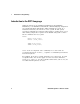
1 Introduction to Programming Introduction to the SCPI Language SCPI, also known as the Standard Commands for Programmable Instruments, is an ASCII-based instrument command language designed for test and measurement instruments. SCPI commands are based on a hierarchical structure, also known as a tree system. In this system, associated commands are grouped together under a common node or root, thus forming subsystems. A portion of the ROUTe subsystem is shown below to illustrate the tree system.
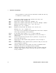
Introduction to Programming 1 SCPI Conventions and Data Formats The following SCPI conventions are used throughout this guide. Angle brackets < > Vertical bar | Square brackets [ ] Parenthesis ( ) Braces { } Items within angle brackets are parameter abbreviations. For example, indicates a specific form of numerical data. Vertical bars separate multiple parameter choices for a given command string. Items within square brackets are optional. The brackets are not sent with the command string.
1 Introduction to Programming Data programmed or queried from the instrument is ASCII. The data may be numerical or character string. Digits with an implied decimal point assumed at the right of the least-significant digit. Example: 273 Digits with an explicit decimal point. Example: 27.3 Digits with an explicit decimal point and an exponent. Example: 2.73E+02 Extended format that includes , , and . Examples: 273 27.3 2.
Introduction to Programming 1 Command Separators A colon ( : ) is used to separate a command keyword from a lower-level keyword. You must insert a blank space to separate a parameter from a command keyword. If a command requires more than one parameter, you must separate adjacent parameters using a comma as shown below. ROUT:CLOS (@101) A semicolon ( ; ) is used to separate commands within the same subsystem and also minimize typing. For example, sending the following command string.
1 Introduction to Programming SCPI Command Terminators A command string sent to the instrument must terminate with a () character. The IEEE-488 End-Of-Identify (EOI) message is interpreted as a character and can be used to terminate a command string in place of a character. A followed by a is also accepted. Command string termination will always reset the current SCPI command path to the root level. IEEE-488.2 Common Commands The IEEE-488.
Introduction to Programming 1 The following command closes channels 101, 103, and 107 on the module. ROUT:CLOS (@101,103,107) // By using ‘,’ for individual channel selection in the same row. The following commands close channels 101, 303, and 405 on the module. ROUT:CLOS (@101,303,405) ROUT:CLOS (@101, 303, 405) // By using ‘,’ for individual channel selection in different row. // The command is still valid with or without the spaces in between each channel.
1 Introduction to Programming When you specify a range of channels, the first and last channel in the range must be valid and any channel within the range that is invalid will be ignored (no error will be generated). Query results are returned in the order they are specified in the list. NOTE 8 When adding a channel list parameter to a query, you must include a space character between the query indicator (?) and channel list parameter such as ROUT:CLOS? (@).
Keysight U2751A USB Modular Switch Matrix Programmer’s Reference Guide 2 SCPI Status Registers SCPI Status Registers 10 Status Byte Register 11 Standard Event Register 12 This chapter explains the SCPI status registers that record various instrument conditions of the U2751A USB modular switch matrix.
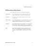
2 SCPI Status Registers SCPI Status Registers The U2751A uses the Status Byte and Standard Event register groups to record a variety of instrument conditions. The figure below shows the relationship between various registers in the U2751A SCPI status system.
SCPI Status Registers 2 Status Byte Register The Status Byte summary register reports conditions from the other status registers. The bits are not cleared when you read the register. Bit Definitions: Status Byte Register Bit number Decimal value Definition 0 Not Used 1 Always zero. 1 Not Used 2 Always zero. 2 Error Queue 4 There is at least one error code in the error queue. Use the SYSTem:ERRor? command to read and clear the error from the queue. 3 Not Used 8 Always zero.
2 SCPI Status Registers Standard Event Register The Standard Event register reports the following types of instrument events: power-on detected, command syntax errors, command execution errors, self-test or calibration errors, query errors, or when an *OPC command is executed. All of these conditions can be reported in the Standard Event summary bit through enable register. To set the enable register mask, key in a decimal value to the register using the event status enable (*ESE)command.
Keysight U2751A USB Modular Switch Matrix Programmer’s Reference Guide 3 DIAGnostic Subsystem DIAGnostic:RELay:CYCLes? 14 DIAGnostic:RELay:CYCLes:CLEar 15 This chapter explains how the DIAGnostic command subsystem operates.
3 DIAGnostic Subsystem DIAGnostic:RELay:CYCLes? Syntax DIAGnostic:RELay:CYCLes? (@) This query returns the cycle count of the relay at the specified channels. Parameter Item Type Range of values Default value NR1 101 through 408 N/A Returned Query Format [,] Example DIAG:REL:CYCL? (@101,104,103) //Queries the number of relay cycles.
DIAGnostic Subsystem 3 DIAGnostic:RELay:CYCLes:CLEar Syntax DIAGnostic:RELay:CYCLes:CLEar (@) This command sets the relay cycle counter of the specified channel(s) to zero. Parameter Item Type Range of values Default value NR1 101 through 408 N/A Example DIAG:REL:CYCL:CLE (@101) NOTE This command is used to clear the relay cycle counter when the user changes a new relay.
3 16 DIAGnostic Subsystem U2751A Programmer’s Reference Guide
Keysight U2751A USB Modular Switch Matrix Programmer’s Reference Guide 4 ROUTe Subsystem ROUTe:CLOSe 18 ROUTe:CLOSe? 19 ROUTe:OPEN 20 ROUTe:OPEN? 21 The ROUTe command subsystem is used to control the matrix relays.
4 ROUTe Subsystem ROUTe:CLOSe Syntax ROUTe:CLOSe (@) This command closes the specified channels in the channel list. The channel number represents the matrix cross-point of a row (one digit) and a column (two digits). For example, channel 308 represents cross-point at row 3 and column 8. Parameter Item Type Range of values Default value NR1 101 through 408 N/A Examples NOTE ROUT:CLOS (@101) // For single channel selection.
ROUTe Subsystem 4 ROUTe:CLOSe? Syntax ROUTe:CLOSe? (@) This query returns the state of the specified channels. It returns "1" if the channel is closed or "0" if the channel is opened. Parameter Item Type Range of values Default value NR1 101 through 408 N/A Returned Query Format [,] Examples ROUT:CLOS? (@101) // Returns 1 if close, 0 if open. Typical Response: 1 ROUT:CLOS? (@101,105,207,304) // Returns 1 if close, 0 if open.
4 ROUTe Subsystem ROUTe:OPEN Syntax ROUTe:OPEN (@) This command opens the specified channels in the channel list. The channel number represents the matrix cross-point of a row (one digit) and a column (two digits). For example, channel 308 represents cross-point at row 3 and column 8. Parameter Item Type Range of values Default value NR1 101 through 408 N/A Examples ROUT:OPEN (@106:303) // By using ‘:’ for multiple channel selection in different row.
ROUTe Subsystem 4 ROUTe:OPEN? Syntax ROUTe:OPEN? (@) This query returns the state of the specified channels. It returns "1" if the channel is opened or "0" if the channel is closed. Parameter Item Type Range of values Default value NR1 101 through 408 N/A Returned Query Format [,] Examples ROUT:OPEN? (@101) // Returns 1 if open, 0 if close. Typical Response: 1 ROUT:OPEN? (@101,205,307,404) // Returns 1 if open, 0 if close.
4 22 ROUTe Subsystem U2751A Programmer’s Reference Guide
Keysight U2751A USB Modular Switch Matrix Programmer’s Reference Guide 5 SYSTem Subsystem SYSTem:CDEScription? 24 SYSTem:ERRor? 25 SYSTem:VERSion? 27 This chapter explains the functions of the SYSTem command subsystem.
5 SYSTem Subsystem SYSTem:CDEScription? Syntax SYSTem:CDEScription? This query returns the slot number and chassis number (chassis ID). Remarks • It is only applicable when the U2751A is used in the modular instrument chassis. • If the U2751A is used as a standalone module, the query will return a default slot number ''+7'' and chassis number ''+0''. • Please refer to the U2781A Modular Instrument Chassis User's Guide for the details.
SYSTem Subsystem 5 SYSTem:ERRor? Syntax SYSTem:ERRor? This query returns the error number and its corresponding message string from the instrument’s error queue. A record of up to 20 errors can be stored in the instrument's error queue. The USB remote interface I/O session has its own interface-specific error queue. Errors that appear in the error queue of the I/O session cause the error. For a complete listing of the U2751A's error messages, refer to Chapter 7, “Error Messages” on page 47.
5 SYSTem Subsystem Returned Query Format , Example SYST:ERR? Typical Response: –330, "Self-test failed" 26 U2751A Programmer’s Reference Guide
SYSTem Subsystem 5 SYSTem:VERSion? Syntax SYSTem:VERSion? This command returns the version of the Standard Commands for Programmable Instruments (SCPI) standard in which the instrument complies with. Returned Query Format Example The command returns a string in the form of "YYYY.V", where "YYYY" represents the year of the version and "V" represents a version for that year (e.g. 1997.0). Typical Response: 1997.
5 28 SYSTem Subsystem U2751A Programmer’s Reference Guide
Keysight U2751A USB Modular Switch Matrix Programmer’s Reference Guide 6 IEEE-488.2 Common Commands *CLS 30 *ESE/*ESE? 31 *ESR? 34 *IDN? 36 *OPC/*OPC? 38 *RST 40 *SRE/*SRE? 41 *STB? 44 *TST? 46 This chapter contains information on the IEEE-488.2 Common (*) Commands supported by the U2751A. It also describes the universal command statements which form the nucleus of the GPIB programming understood by all instruments in the network.
6 IEEE-488.2 Common Commands *CLS Syntax *CLS This command is used to clear the event registers in all register groups and also clears the error queue. NOTE For more information on the system registers, refer to Chapter 2, “SCPI Status Registers” on page 9. Example The following command clears the event register bits.
IEEE-488.2 Common Commands 6 *ESE/*ESE? Syntax *ESE This command enables the bits in the enable register for the Standard Event register group. The selected bits are then reported to bit 5 of the Status Byte register. *ESE? This will query the Standard Event enable register group. NOTE For more information on the system registers, refer to Chapter 2, “SCPI Status Registers” on page 9.
6 IEEE-488.2 Common Commands Remarks • The following table lists the bit definitions for the Standard Event register. Bit number Decimal value Definition 0 Operation Complete 1 All commands prior to and including *OPC have been executed. 1 Not Used 2 Always zero. 2 Query Error 4 The instrument tried to read the output buffer but it was empty. Or, a new command line was received before a previous query has been read.
IEEE-488.2 Common Commands 6 Returned Query Format The query command reads the enable register and returns a decimal value that corresponds to the binary-weighted sum of all the bits set in the register. For example, if bit 3 (decimal value = 8) and bit 7 (decimal value = 128) are enabled, the query command will return ''+136''. Examples The following command enables bit 4 (decimal value = 16) in the enable register.
6 IEEE-488.2 Common Commands *ESR? Syntax *ESR? This query returns the value of the event register of the Standard Event status group. Once it is read, it will be cleared automatically. NOTE For more information on the system registers, refer to Chapter 2, “SCPI Status Registers” on page 9. Remarks • The following table lists the bit definitions for the Standard Event register.
IEEE-488.2 Common Commands 6 • For any event to be reported on the Status Byte register group, the corresponding bits in the event register must be enabled using the *ESE command. • Once a bit is set, it will remain set until cleared by reading the event register or the clear status (*CLS) command. Returned Query Format The query command reads the event register and returns a decimal value that corresponds to the binary-weighted sum of all the bits set in the register.
6 IEEE-488.2 Common Commands *IDN? Syntax *IDN? This command reads the instrument's identification string which contains four comma-separated fields. The first field is the manufacturer's name, the second is the model number of the instrument, the third is the serial number, and the fourth is the firmware revision which contains three firmwares separated by dashes. NOTE For more information on the system registers, refer to Chapter 2, “SCPI Status Registers” on page 9.
IEEE-488.2 Common Commands 6 Example The following query returns the instrument's identification string. *IDN? Typical Response: KEYSIGHT TECHNOLOGIES,U2751A,MY12345678,V1.00-1.00-1.00 If the system is unable to recognize the model number or serial number, the *IDN? command will return the default value of the model and serial number. Please perform self-test for error check. Typical Response: KEYSIGHT TECHNOLOGIES,U2751X,MY1234567X,V1.00-1.00-1.
6 IEEE-488.2 Common Commands *OPC/*OPC? Syntax *OPC The command is mainly used for program synchronization. It causes the instrument to set the OPC bit (bit 0) of the Standard Event Status register when the instrument has completed all pending operation sent before the *OPC command. *OPC? This query returns "1" to the output buffer at the completion of all the pending operation. *OPC? command does not suspend processing of commands.
IEEE-488.2 Common Commands 6 Examples The following command waits until the closing of channel 101 command has been executed and then sets the “Operation Complete” bit.
6 IEEE-488.2 Common Commands *RST Syntax *RST This command is used to reset the relays. It will turn all relays to open state. Example The following command resets the instrument.
IEEE-488.2 Common Commands 6 *SRE/*SRE? Syntax *SRE This command enables the bits in the enable register for the Status Byte register group. Once enabled, the corresponding bits may generate a Request for Service (RQS) in the Status Byte register. This RQS event may generate a "call back" to your application as a type of asynchronous interrupt.
6 IEEE-488.2 Common Commands Remarks • The following table lists the bit definitions for the Status Byte register. Bit number Decimal value Definition 0 Not Used 1 Always zero. 1 Not Used 2 Always zero. 2 Error Queue 4 There is at least one error code in the error queue. Use the SYSTem:ERRor? command to read and clear the error from the queue. 3 Not Used 8 Always zero. 4 Message Available 16 Data is available in the instrument's output buffer.
IEEE-488.2 Common Commands 6 Examples The following command enables bit 4 (decimal value = 16) in the enable register. *SRE 16 The following query returns the bits enabled in the register.
6 IEEE-488.2 Common Commands *STB? Syntax *STB? Queries the condition register for the Status Byte register group. The bits are not cleared when you read the register. Remarks • The following table lists the bit definitions for the Status Byte register. Bit number Decimal value Definition 0 Not Used 1 Always zero. 1 Not Used 2 Always zero. 2 Error Queue 4 There is at least one error code in the error queue. Use the SYSTem:ERRor? command to read and clear the error from the queue.
IEEE-488.2 Common Commands 6 Returned Query Format The query command reads the condition register and returns a decimal value which corresponds to the binary-weighted sum of all the bits set in the register (refer to the table under Remarks). For example, if bit 1 (decimal value = 2) and bit 4 (decimal value = 16) are set (and the corresponding bits are enabled), this command will return "+18". Example The following command reads the condition register (bits 3 and 4 are set).
6 IEEE-488.2 Common Commands *TST? Syntax *TST? This query command performs a self-test of the instrument and returns a pass/fail indication. This self-test is the same as the self-test conducted when the matrix is powered-on. When self-test fails, error will be reported. Returned Query Format The command returns "+0" (all tests passed) or "+1" (one or more tests failed). Example The following command performs a self-test and returns a pass/fail indication.
Keysight U2751A USB Modular Switch Matrix Programmer’s Reference Guide 7 Error Messages Error Messages 48 Error List 48 This U2751A SCPI command errors are summarized in this chapter.
7 Error Messages Error Messages Error messages are created once a command error or an erroneous condition has been detected. • Errors are retrieved in first-in, first-out (FIFO) order. • Errors are cleared as you read them. • If too many errors occur, the last error stored in the queue (the most recent error) will be replaced with –350, "Queue overflow". No additional errors will be stored until you remove the errors from the queue.
Error Messages 7 Table 7-1 Command errors (continued) Error Command errors (these errors set the Standard Event Status register bit #5) –112 Program mnemonic too long The header contains more than 12 characters. –113 Undefined header A command was received that is not valid. You may have misspelled the command or it may not be a valid command. If you are using the short form of the command, remember that it may contain up to four letters.
7 Error Messages The following table shows the list of device-specific errors. Table 7-3 Device-specific errors Error Device-specific errors (these errors set the Standard Event Status register bit #3) –330 Self-test failed The self-test fails. –350 Queue overflow The error queue is full and another error has occurred which could not be recorded. The list of query errors is shown in the following table.
Error Messages 7 The table below contains the list of instrument errors. Table 7-5 Instrument errors Error Instrument errors (these errors set the Standard Event Status register bit #3) +112 Channel list: channel number out of range An input of less than 1 or more than 4 for the row numbers will cause this error message to appear such as 001and 501. Also, the column numbers which are less than 1 or more than 8 will generate this error such as 100 and 109.
7 52 Error Messages U2751A Programmer’s Reference Guide
www.keysight.
This information is subject to change without notice. © Keysight Technologies 2008, 2015 Edition 2, January 2015 *U2751-90022* U2751-90022 www.keysight.