Agilent U2751A USB Modular Switch Matrix User’s and Service Guide Agilent Technologies
Notices ® Agilent Technologies, Inc., 2008–2013 Warranty No part of this manual may be reproduced in any form or by any means (including electronic storage and retrieval or translation into a foreign language) without prior agreement and written consent from Agilent Technologies, Inc. as governed by United States and international copyright laws. The material contained in this document is provided “as is,” and is subject to being changed, without notice, in future editions.
Safety Symbols The following symbols on the instrument and in the documentation indicate precautions which must be taken to maintain safe operation of the instrument.
General Safety Information WA R N I N G • Do not operate the device around explosive gas, vapor, or dust. • Observe all markings on the device before establishing any connection. • The device is under CAT I measurement category, do not connect the 25-pin connector to MAINS. CAT I: Maximum working voltage: Standalone 35 Vrms Modular (Used with U2781A) 180 Vrms Maximum transient voltage: 300 Vrms • Do not measure higher than the rated voltage (as marked on the device).
Environmental Conditions This instrument is designed for indoor use and in an area with low condensation. The table below shows the general environmental requirements for this instrument. CAUTION Requirements Operating temperature 0 °C to 50 °C Operating humidity 20% to 85% RH non-condensing Storage temperature –20 °C to 70 °C Storage humidity 5% to 90% RH non-condensing The U2751A USB modular switch matrix complies with the following safety and EMC requirements.
Regulatory Markings The CE mark is a registered trademark of the European Community. This CE mark shows that the product complies with all the relevant European Legal Directives. The C-tick mark is a registered trademark of the Spectrum Management Agency of Australia. This signifies compliance with the Australia EMC Framework regulations under the terms of the Radio Communication Act of 1992. ICES/NMB-001 indicates that this ISM device complies with the Canadian ICES-001.
Waste Electrical and Electronic Equipment (WEEE) Directive 2002/96/EC This instrument complies with the WEEE Directive (2002/96/EC) marking requirement. This affixed product label indicates that you must not discard this electrical/electronic product in domestic household waste. Product Category: With reference to the equipment types in the WEEE directive Annex 1, this instrument is classified as a “Monitoring and Control Instrument” product. The affixed product label is as shown below.
In This Guide… 1 Getting Started This chapter provides an overview of the U2751A USB modular switch matrix, which includes the product outlook, product dimensions, and product layout. This chapter also contains instructions on how to install and configure the U2751A. 2 Operation and Features This chapter describes the operation and features that are offered by the U2751A, such as switch controls and relay usage monitoring.
Declaration of Conformity (DoC) The Declaration of Conformity (DoC) for this instrument is available on the Web site. You can search the DoC by its product model or description. http://regulations.corporate.agilent.com/DoC/search.htm NOTE U2751A User’s and Service Guide If you are unable to search for the respective DoC, please contact your local Agilent representative.
THIS PAGE HAS BEEN INTENTIONALLY LEFT BLANK.
Contents List of Figures XIII List of Tables 1 XV Getting Started Introduction 1 2 Product at a Glance Product Outlook 3 3 Product Dimensions 5 Dimensions Without Bumpers 5 Dimensions With Bumpers 6 Standard Shipped Items 7 Inspection and Maintenance 8 Initial Inspection 8 Electrical Check 8 General Maintenance 8 Installation and Configuration 9 U2751A DSub Connector 10 U2922A Terminal Block 11 U2922A Terminal Block Installation 14 55-Pin Backplane Connector Pin Configuration Chassis Installation
Contents Relay Cycle Counter 24 System-Related Operation 25 Self-Test 25 Error Conditions 25 SCPI Commands for System-Related Tasks 3 Characteristics and Specifications Product Characteristics Product Specifications 4 Service Information 27 28 30 33 Checking Defective Relay(s) 34 Replaceable Parts 35 Disassembly Instructions 36 Reassembly Instructions 38 Contacting Agilent Technologies XII 26 38 U2751A User’s and Service Guide
List of Figures Figure 1-1. Figure 1-2. Figure 1-3. Figure 1-4. Figure 1-5. Figure 2-1. Figure 2-2. Figure 2-3. Figure 4-4.
THIS PAGE HAS BEEN INTENTIONALLY LEFT BLANK.
List of Tables Table 1-1. Pin assignments 10 Table 1-2. Synchronous Simultaneous Interface (SSI) connector pin description 16 Table 3-3. Electrical and mechanical specifications update per attached data sheet 30 Table 3-1. Electrical and mechanical specifications update per attached data sheet (continued) 31 Table 4-2.
THIS PAGE HAS BEEN INTENTIONALLY LEFT BLANK.
U2751A USB Modular Switch Matrix User’s and Service Guide 1 Getting Started Introduction 2 Product at a Glance 3 Product Outlook 3 Product Dimensions 5 Dimensions Without Bumpers 5 Dimensions With Bumpers 6 Standard Shipped Items 7 Inspection and Maintenance 8 Initial Inspection 8 Electrical Check 8 General Maintenance 8 Installation and Configuration 9 U2751A DSub Connector 10 U2922A Terminal Block 11 U2922A Terminal Block Installation 14 55-Pin Backplane Connector Pin Configuration 16 Chassis Installatio
1 Getting Started Introduction The U2751A USB modular switch matrix offers a high quality, low cost switching solution for automated test. It can operate as a standalone or modular unit when used with the U2781A USB modular instrument chassis. The U2751A is a compact 4×8, two-wire modular switch matrix which is controlled remotely over a USB interface via the Agilent Measurement Manager software. The U2751A can also be programmed using the provided drivers or via SCPI commands.
Getting Started 1 Product at a Glance Product Outlook Top View Bumpers U2751A User’s and Service Guide 3
1 Getting Started Front View USB indicator Power indicator DSub connector Rear View 55-pin backplane connector USB inlet Fastening hole for USB cable with locking mechanism Power inlet 4 U2751A User’s and Service Guide
Getting Started 1 Product Dimensions Dimensions Without Bumpers Top View 105.00 mm 175.00 mm Front View 25.
1 Getting Started Dimensions With Bumpers Top View 117.00 mm 180.00 mm Front View 41.
Getting Started 1 Standard Shipped Items Verify that you have received the following items with your unit. If anything is missing or damaged, please contact the nearest Agilent Sales Office.
1 Getting Started Inspection and Maintenance Initial Inspection When you receive your U2751A, inspect the unit for any obvious damage such as broken terminals or cracks, dents, and scratches on the casing that may occur during shipment. If any damage is found, notify the nearest Agilent Sales Office immediately. The front of this manual contains the warranty information. Keep the original packaging in case the U2751A has to be returned to Agilent in the future.
Getting Started 1 Installation and Configuration Follow the step-by-step instructions shown in the Agilent USB Modular Products and Systems Quick Start Guide to get started with the preparations and installation of your U2751A. NOTE U2751A User’s and Service Guide You need to install the IVI-COM driver if you are going to use the U2751A with Agilent VEE Pro, LabVIEW, or Microsoft® Visual Studio®.
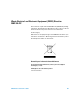
1 Getting Started U2751A DSub Connector The U2751A is equipped with one 25-pin male DSub connector as shown in Figure 1- 1. Figure 1-1 25-pin male DSub connector Pin Assignments Table 1-1 Pin assignments Pin Description Pin Description 18 R1H 10 C3H 19 R1L 11 C3L 20 R2H 8 C4H 21 R2L 9 C4L 16 R3H 5 C5H 17 R3L 6 C5L 22 R4H 3 C6H 23 R4L 4 C6L 24 C1H 1 C7H 25 C1L 2 C7L 12 C2H 14 C8H 13 C2L 15 C8L 7 GND R represents “Row” and C represents “Column”.
Getting Started 1 U2922A Terminal Block The U2922A terminal block is an optional accessory to be used with the U2751A. The U2922A which weighs approximately 100 g and has screw-type terminals, offers you a convenient and simple way of making connection to the switch matrix for prototyping applications or an actual system deployment. It allows the user to configure a wide variety of routing options and matrix topologies.
1 Getting Started The outlook and dimensions of the U2922A are shown in Figure 1- 3 and Figure 1- 4.
Getting Started 1 Rear View 85.00 mm 23.00 mm Top View 90.00 mm Front View 105.00 mm Side View 85.00 mm 105.00 mm 23.00 mm 23.
1 Getting Started U2922A Terminal Block Installation This section provides the recommended procedure for connecting the U2922A terminal block to the U2751A. • The maximum working voltage of the U2751A with the terminal block for standalone is 35 Vrms and for modular (when used with the U2781A) is 180 Vrms. WA R N I N G • The maximum transient voltage is 300 Vrms. • Do not remove the retractable cover from the U2922A terminal block during operation to avoid any unexpected hazard.
Getting Started 1 Snap-fit clasp of the retractable cover and the housing Close your terminal block by slotting in the retractable cover. Check the snap-fit clasp on the cover and the housing to ensure correct orientation of the retractable cover before slotting it in. Turn over the U2922A with the retractable cover facing downwards. Then, insert the U2922A to the U2751A as shown. Tighten the jack screws using a screw driver to secure the connection.
1 Getting Started 55-Pin Backplane Connector Pin Configuration The 55-pin backplane connector is used when the U2751A module is inserted into the U2781A USB modular instrument chassis. For more details, refer to the Agilent U2781A USB Modular Instrument Chassis User's Guide.
Getting Started 1 Chassis Installation The L-Mount kit is to be installed to your U2751A module. The following instructions describe the simple procedure of installing the L-Mount kit and your module in the U2781A chassis. 1 Unpack the L-Mount kit from its packaging. 2 Remove your U2751A module from the bumper casing. 3 Using a Phillips screwdriver, fasten the L-Mount kit to your U2751A module.
1 Getting Started THIS PAGE HAS BEEN INTENTIONALLY LEFT BLANK.
U2751A USB Modular Switch Matrix User’s and Service Guide 2 Operation and Features Power Up 20 Switch Control 21 Relay Cycle Counter 24 System-Related Operation 25 Self-Test 25 Error Conditions 25 SCPI Commands for System-Related Tasks 26 This chapter describes the features and operation of the U2751A.
2 Operation and Features Power Up Take note of the following when you power up the U2751A. • The U2751A can only be operated via the USB interface. • Before you can control the U2751A, you need to install the hardware driver and the IO Libraries Suite 14.2 or higher. Both of these are included when you purchase the U2751A. Refer to the Agilent USB Modular Products and Systems Quick Start Guide for the installation procedure. • On the front panel of the U2751A, there are two LED indicators.
Operation and Features 2 Switch Control A matrix switch connects multiple inputs to multiple outputs. A matrix is arranged in rows and columns. For example, the U2751A is a 4×8 matrix that can be used to connect four sources to eight test points as shown in Figure 2- 1. Any column can be connected to any row by activating the corresponding relay that connects the column to the row as shown in Figure 2- 1.
2 Operation and Features Figure 2-2 Panel view of the Agilent Measurement Manager Agilent Measurement Manager Operation Launch the Agilent Measurement Manager software and select the Matrix tab. The keyboard shortcut key is Ctrl+M. Connect the instruments and devices as per your application. Key in the names of the instruments and devices in the available text boxes. Click the cross-point circles on the software to toggle the contact on or off.
Operation and Features 2 SCPI Commands The following examples show the SCPI commands for executing the closing and opening of the relays. Example 1, Make contact at channel 302 -> *CLS; *RST // Resets the switch to the default power-on state. This command can be ignored if this operation is not required. -> ROUTe:CLOSe (@302) // Closes the relay at row 3, column 2. Example 2, Break contact at channel 302 -> ROUTe:OPEN (@302) // Opens the relay at row 3, column 2.
2 Operation and Features Relay Cycle Counter Figure 2-3 Panel view of the relay cycle counter Agilent Measurement Manager Operation At the main panel, select the Relay Cycle Counter tab. The panel in Figure 2- 3 will be displayed. The keyboard shortcut key is Ctrl+R. This feature allows the user to carry out preventive maintenance, which is to replace those relays that are at the end of their life span. Relay cycles that are above a certain limit will be highlighted in red.
Operation and Features 2 System-Related Operation This section provides information on system-related topics such as executing a self-test, performing self-calibration routine, and reading error conditions. NOTE Do not connect any terminal block or cables prior to performing self-test process. Self-Test To perform the self-test, proceed as follows. Agilent Measurement Manager Operation Ensure that the switch terminals are not connected to any instrument. Turn on the U2751A.
2 Operation and Features SCPI Commands for System-Related Tasks The following examples show the SCPI commands for performing certain system-related tasks. Example 4, Performing system-related tasks -> *CLS; *RST // Resets the switch to the default power-on state. This command can be ignored if this operation is not required. -> *TST? // Executes the self-test. <- +0 // Returns a +0 if the test pass else it will return a +1 if it fails.
U2751A USB Modular Switch Matrix User’s and Service Guide 3 Characteristics and Specifications Product Characteristics 28 Product Specifications 30 This chapter specifies the characteristics, environmental conditions, and specifications of the U2751A.
3 Characteristics and Specifications Product Characteristics REMOTE INTERFACE1 • Hi-Speed USB 2.0 • USBTMC 488.
Characteristics and Specifications 3 WARRANTY • Please refer to http://www.agilent.com/go/warranty_terms • 3 years for the product • 3 months for the product’s standard accessories, unless otherwise specified • Please take note that for the product, the warranty does not cover: • Damage from contamination • Normal wear and tear of mechanical components • Manuals CALIBRATION Annual calibration is not required 1 For remote connections using Agilent E5813A, refer to Chapter 1.
3 Characteristics and Specifications Product Specifications Table 3-3 Electrical and mechanical specifications update per attached data sheet U2751A Without U2922A Terminal Block Channels/configurations With U2922A Terminal Block 4×8, 2-wire Switch type Armature latching Input characteristics (per channel) Max volts1 Standalone Modular (Used with U2781A) 42 VDC/35 Vrms 180 VDC/180 Vrms Max transient voltage 300 Vrms Max current Switch current Carry current 2A 2A Power (W, VA)2 60 W, 62.
Characteristics and Specifications 3 Table 3-1 Electrical and mechanical specifications update per attached data sheet (continued) General characteristics Relay life, typical No load 10 V, 100 mA Related load 100 M 10 M 100 k Open/close time 4 ms/4 ms 1 DC or AC rms, channel-to-channel or channel-to-earth. 2 Limited to 6 W channel resistance power loss per module. 3 50 Ω source, 50 Ω load, differential measurements verified with a 4-port network analyzer (Sdd21).
3 Characteristics and Specifications THIS PAGE HAS BEEN INTENTIONALLY LEFT BLANK.
U2751A USB Modular Switch Matrix User’s and Service Guide 4 Service Information Checking Defective Relay(s) 34 Replaceable Parts 35 Disassembly Instructions 36 Reassembly Instructions 38 Contacting Agilent Technologies 38 This chapter provides guidelines for returning your instrument to Agilent for service or repair, and for servicing it yourself. A list of replaceable parts is also provided.
4 Service Information Checking Defective Relay(s) NOTE It is recommended to have the relay(s) checked when it reaches 10 million cycle counts. The relay cycle count can be obtained by using the Agilent Measurement Manager or sending the following SCPI command: DIAGnostic:RELay:CYCLes? (@) To check for any defective relay, the equipment required is a digital multimeter with continuity feature. 1 Close the particular relay(s). For example: The relay located at Row x Column y.
Service Information 4 Replaceable Parts This section contains the information for ordering replacement parts for your instrument. To order the parts, please do the following. • Contact your nearest Agilent Sales Office or Service Center. • Provide the part number for the relay. • Provide the instrument model and serial number. The part number of the replaceable part and its description are shown in the table below.
4 Service Information Disassembly Instructions Remove the screws and nuts as shown. Take the measurement board and carrier board out from the module. Remove the screws as indicated.
Service Information 4 Separate the carrier and measurement board. There are 32 relays as shown. Turn to the opposite side of the measurement board and ensure that only the defective relays are desoldered.
4 Service Information Reassembly Instructions The reassembly process is simply the reverse of disassembly. Contacting Agilent Technologies Types of Service Available If your instrument fails during the warranty period, Agilent will replace the unit for free. The replacement units will be shipped with new calibration certificates. NOTE Every replacement unit has its own serial number. The serial number of the defective unit does not transfer to the replacement unit.
Index # cross-point, 2 L 55-pin backplane connector pin, 16 D LED indicators, 20 L-Mount kit, 7, 17 A DC AC characteristics, 30 Agilent Measurement Manager help file, 2 operation, 22, 24, 25, 25 panel view, 22 relay cycle count, 34, 37 Agilent U2751A USB Modular Switch Matrix, Quick Reference Card, 7 B bandwidth, 30 bumper, 8 bumper casing, 8, 17 isolation, 30 defective relays, check, 34 DIAGnostic:RELay:CYCLes? (@), 34 device under test. See DUT disassembly.
Index power cord, 7 power up, U2751A, 20 precautions, ESD, IV, 35 product characteristics dimensions, 28 EMC compliance, 28 I/O connector, 28 operating enviroment, 28 power consumption, 28 remote interface, 28 safety compliance, 28 shock and vibration, 28 storage compliance, 28 warranty, 29 weight, 28 product dimensions with bumper, 6 without bumper, 5 product outlook front view, 4 rear view, 4 top view, 3 product specifications AC characteristics, 30 general characteristics, 31 general specifications, 30
www.agilent.