User's Guide.book Page I Friday, August 8, 2008 9:11 AM Agilent U2741A USB Modular 5.
User's Guide.book Page II Friday, August 8, 2008 9:11 AM Notices ® Agilent Technologies, Inc. , 2008 Warranty No part of this manual may be reproduced in any form or by any means (including electronic storage and retrieval or translation into a foreign language) without prior agreement and written consent from Agilent Technologies, Inc. as governed by United States and international copyright laws.
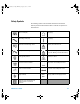
User's Guide.book Page III Friday, August 8, 2008 9:11 AM Safety Symbols The following symbols on the instrument and in the documentation indicate precautions which must be taken to maintain safe operation of the instrument.
User's Guide.book Page IV Friday, August 8, 2008 9:11 AM General Safety Information IV WARN IN G • Do not use the device if it is damaged. Before you use the device, inspect the casing. Look for cracks or missing plastic. Do not operate the device around explosive gas, vapor, or dust. • Always use the device with the cables provided. • Observe all markings on the device before establishing any connection. • Turn off the device and application system power before connecting to the I/O terminals.
User's Guide.book Page V Friday, August 8, 2008 9:11 AM Environmental Conditions This instrument is designed for indoor use and in an area with low condensation. The table below shows the general environmental requirements for this instrument.
User's Guide.book Page VI Friday, August 8, 2008 9:11 AM Regulatory Markings The CE mark is a registered trademark of the European Community. This CE mark shows that the product complies with all the relevant European Legal Directives. The C-tick mark is a registered trademark of the Spectrum Management Agency of Australia. This signifies compliance with the Australia EMC Framework regulations under the terms of the Radio Communication Act of 1992.
User's Guide.book Page VII Friday, August 8, 2008 9:11 AM Waste Electrical and Electronic Equipment (WEEE) Directive 2002/96/EC This instrument complies with the WEEE Directive (2002/96/EC) marking requirement. This affixed product label indicates that you must not discard this electrical/electronic product in domestic household waste. Product Category: With reference to the equipment types in the WEEE directive Annex 1, this instrument is classified as a “Monitoring and Control Instrument” product.
User's Guide.book Page VIII Friday, August 8, 2008 9:11 AM In This Guide… 1 Getting Started This chapter provides an overview of the U2741A USB modular digital multimeter, the product outlook, product dimension, and product layout. This chapter contains instructions on how to install and configure to get started with the U2741A. 2 Operation and Features In this chapter, you will get to learn more about the operations and features that are offered by the U2741A.
User's Guide.book Page IX Friday, August 8, 2008 9:11 AM DECLARATION OF CONFORMITY According to EN ISO/IEC 17050-1:2004 Generic example Manufacturer’s Name: Manufacturer’s Address: Agilent Technologies Microwave Products (M) Sdn.
User's Guide.book Page X Friday, August 8, 2008 9:11 AM Product Regulations EMC Performance Criteria IEC 61326-1:2002 / EN 61326-1:1997+A1:1998+A2:2001+A3:2003 CISPR 11:1990 / EN 55011:1990 – Group 1 Class A IEC 61000-4-2:1995 / EN 61000-4-2:1995 (ESD 4kV CD, 8kV AD) IEC 61000-4-3:1995 / EN 61000-4-3:1996 (3V/m, 80% AM) IEC 61000-4-4:1995 / EN 61000-4-4:1995 (EFT 0.5kV line-line, 1kV line-earth) IEC 61000-4-5:1995 / EN 61000-4-5:1995 (Surge 0.
User's Guide.book Page XI Friday, August 8, 2008 9:11 AM Contents 1 Getting Started Introduction 1 2 Product at a Glance Product Outlook 3 3 Product Dimensions 5 Dimensions without Bumpers 5 Dimensions with Bumpers 6 Standard Purchase Items 7 Inspection and Maintenance 8 Initial Inspection 8 Electrical Check 8 General Maintenance 9 Installation and Configuration 10 Installation 10 A. Check Your System 11 B. Install the IO Libraries Suite 12 C. Install the Module Driver 13 D.
User's Guide.
User's Guide.
User's Guide.
User's Guide.
User's Guide.
User's Guide.
User's Guide.
User's Guide.book Page 1 Friday, August 8, 2008 9:11 AM U2741A USB Modular 5.5 Digits Digital Multimeter User’s Guide 1 Getting Started Introduction 2 Product at a Glance 3 Product Outlook 3 Product Dimensions 5 Dimensions without Bumpers 5 Dimensions with Bumpers 6 Standard Purchase Items 7 Inspection and Maintenance 8 Initial Inspection 8 Electrical Check 8 General Maintenance 9 Installation and Configuration 10 Installation 10 A. Check Your System 11 B. Install the IO Libraries Suite 12 C.
User's Guide.book Page 2 Friday, August 8, 2008 9:11 AM 1 Getting Started Introduction The Agilent U2741A is a 5.5 digits digital multimeter that can operate as standalone or as a modular unit when used with the U2781A USB modular instrument chassis.
User's Guide.
User's Guide.
User's Guide.book Page 5 Friday, August 8, 2008 9:11 AM Getting Started 1 Product Dimensions Dimensions without Bumpers Top view 105.00 mm 175.00 mm 11.50 mm Front view 25.
User's Guide.book Page 6 Friday, August 8, 2008 9:11 AM 1 Getting Started Dimensions with Bumpers Top view 117.00 mm 180.00 mm 8.60 mm Front view 41.
User's Guide.book Page 7 Friday, August 8, 2008 9:11 AM Getting Started 1 Standard Purchase Items Verify that you have received the following items with your unit. If anything is missing or damaged, please contact the nearest Agilent Sales Office.
User's Guide.book Page 8 Friday, August 8, 2008 9:11 AM 1 Getting Started Inspection and Maintenance Initial Inspection When you receive your U2741A, inspect the unit for any obvious damage such as broken terminals or cracks, dents, and scratches on the casing that may occur during shipment. If any damage is found, notify the nearest Agilent Sales Office immediately. The front of this manual contains the warranty information.
User's Guide.book Page 9 Friday, August 8, 2008 9:11 AM Getting Started 1 General Maintenance General maintenance N O TE Any repair that is not covered in your modular product manuals should only be performed by qualified personnel. 1 Power off your module and remove the power cord and I/O cable from your device. 2 Remove your module from the bumper casing. 3 Shake out any dirt that may have accumulated on the module. 4 Wipe your module with a dry cloth and install the bumper back in place.
User's Guide.book Page 10 Friday, August 8, 2008 9:11 AM 1 Getting Started Installation and Configuration Installation Follow the step-by-step instructions shown in the following flowchart to get started with the preparations and installations of your U2741A. N O TE You need to install the IVI-COM driver if you are going to use the U2741A with Agilent VEE Pro, LabVIEW, or Microsoft® Visual Studio®. A. Check Your System B. Install the IO Libraries Suite C. Install the Module Driver D.
User's Guide.book Page 11 Friday, August 8, 2008 9:11 AM Getting Started 1 A. Check Your System Prior to any installation or configuration, please ensure that your PC meets the following minimum system requirements. Processor 1.6 GHz Pentium® IV or higher Operating system Windows® XP Professional or Home Edition (Service Pack 1 or later), or Windows® 2000 Professional (Service Pack 4 or later) Browser Microsoft® Internet Explorer 5.
User's Guide.book Page 12 Friday, August 8, 2008 9:11 AM 1 Getting Started B. Install the IO Libraries Suite The IO Libraries Suite 14.2 or higher is available on the Agilent Automation-Ready CD that comes with the standard purchase of the U2741A. N O TE • If you do not have the Agilent Automation-Ready CD, obtain the IO Libraries Suite 14.2 or higher at http://www.agilent.com/find/iolib. • Disconnect any USB instruments or connectivity interface from your PC.
User's Guide.book Page 13 Friday, August 8, 2008 9:11 AM Getting Started N O TE 1 For detailed installation instructions, refer to the Agilent IO Libraries Suite Getting Started Guide at http://www.agilent.com/find/iolib. C. Install the Module Driver N O TE Please ensure that there are no instruments connected to the PC when installing the driver. 1 Verify that your PC meets the minimum system requirements as stated in “A. Check Your System” on page 11.
User's Guide.book Page 14 Friday, August 8, 2008 9:11 AM 1 Getting Started 4 If the menu does not launch automatically, go to Start > Run (on the Windows Start menu) and type :\ Driver\Hardware\setup_Hw.exe where is your CD-ROM drive location. Click OK to begin the installation. 5 Follow the instructions on the screen and click Next to proceed. 6 Click Install to begin the installation. Follow the instructions on the screen to proceed with the installation.
User's Guide.book Page 15 Friday, August 8, 2008 9:11 AM Getting Started 1 3 If the installation menu does not appear after a few seconds, go to Start > Run and type :\ Application\Modular Instruments Measurement Manager\setup.exe where is your CD-ROM drive location. 4 Click OK to begin the installation. 5 If you do not have any of the prerequisites installed, the InstallShield Wizard software prerequisite will appear.
User's Guide.book Page 16 Friday, August 8, 2008 9:11 AM 1 Getting Started E. Connect the Module to Your PC N O TE Ensure that the AMM is installed before proceeding. 1 After the installations have completed, connect the power cord to the AC/DC power adapter. The AC/DC power adapter requirements are 100 to 240 VAC, 50/60 Hz, with an output voltage of +12 VDC. 2 Insert the DC output plug from the AC/DC power adapter to the power jack on the rear panel of the U2741A.
User's Guide.book Page 17 Friday, August 8, 2008 9:11 AM Getting Started 1 5 Select Install the software automatically (Recommended) and click Next. 6 A warning message will appear on the Hardware Installation window. Click Continue Anyway to proceed with the installation of the U2741A.
User's Guide.book Page 18 Friday, August 8, 2008 9:11 AM 1 Getting Started N O TE If you do not wish to receive similar warning messages in the future, follow the instructions below. • Go to Start > Control Panel and double-click System. • Select the Hardware tab and click Driver Signing on the Drivers panel. The Driver Signing Options dialog box will appear. • Select Ignore to disable the warning message. 7 Click Finish to complete the installation. 8 The Assign USB device alias window will appear.
User's Guide.book Page 19 Friday, August 8, 2008 9:11 AM Getting Started 1 9 The system will perform a firmware version check on your connected module. a If the module firmware version is the same as the installed version on the PC, it will not perform any firmware download, and the U2741A is then ready for use. b If the module firmware version differs from the installed version on the PC, the following message box will appear. Firmware versions (V1.00 and V1.
User's Guide.book Page 20 Friday, August 8, 2008 9:11 AM 1 Getting Started c Click Yes to begin the firmware download. The following message box will appear indicating the download in progress. N O TE i Ensure that you do not remove the USB and power connection until the firmware download has completed. ii It is recommended to power cycle the U2741A after every firmware upgrade. d Your U2741A is ready for use once the firmware upgrade has completed.
User's Guide.book Page 21 Friday, August 8, 2008 9:11 AM Getting Started 1 F. Verify Your Module Connection The Agilent Connection Expert is one of the utilities in the IO Libraries. The Connection Expert configures the connected instruments and enables communication. It is able to automatically detect the U2741A devices plugged into the PC. 1 Go to Start > All Programs > Agilent IO Libraries Suite > Agilent Connection Expert to launch the Connection Expert.
User's Guide.book Page 22 Friday, August 8, 2008 9:11 AM 1 Getting Started 5 A successful communication between the Connection Expert and the U2741A will indicate that the instrument is installed correctly.
User's Guide.book Page 23 Friday, August 8, 2008 9:11 AM Getting Started 1 G. Launch Your Agilent Measurement Manager N O TE • The IO Control will launch automatically when you start your PC. • Launching the Measurement Manager without the IO Control running will cause the Measurement Manager to fail to detect or establish any connection with the U2741A connected to your PC. • To run the IO Control, go to Start > All Programs > Agilent IO Libraries Suite > Utilities > IO Control.
User's Guide.book Page 24 Friday, August 8, 2008 9:11 AM 1 Getting Started N O TE 24 For more information on how to use the Measurement Manager, refer to the Agilent Measurement Manager help file.
User's Guide.book Page 25 Friday, August 8, 2008 9:11 AM Getting Started 1 Instrument Configuration 55-Pin Backplane Connector Pin Configuration The 55- pin backplane connector is used when the U2741A module is inserted into the U2781A USB modular instrument chassis. For more details, refer to the Agilent U2781A USB Modular Instrument Chassis User's Guide.
User's Guide.book Page 26 Friday, August 8, 2008 9:11 AM 1 Getting Started Table 1-1 SSI connector pin description SSI timing signal Functionality CLK10M 10 MHz clock source STAR_TRIG Star trigger GA0,GA1,GA2 Geographical address pin Chassis Installation The L- Mount kit is to be installed to your U2741A module. The following instructions describe the simple procedure of installing the L- Mount kit and your module in the chassis. 1 Unpack the L- Mount kit from the packaging.
User's Guide.book Page 27 Friday, August 8, 2008 9:11 AM U2741A USB Modular 5.
User's Guide.book Page 28 Friday, August 8, 2008 9:11 AM 2 Operation and Features Powering Up Take note of the following when you power up the U2741A. • The U2741A can only be operated via the USB interface. • Before you can control the U2741A, you need to install the hardware driver and the IO Libraries Suite 14.2 or higher. Both of these are included when you purchase the U2741A. Refer to Chapter 1, “B. Install the IO Libraries Suite” on page 12 and “C.
User's Guide.book Page 29 Friday, August 8, 2008 9:11 AM Operation and Features 2 Making Measurements The following pages show how to make measurement connections and how to select measurement functions from the front panel for each of the measurement functions. Measuring DC Voltage The DC voltage measurement function has the following features: • Five ranges to select: 100 mV, 1 V, 10 V, 100 V, and 300 V or, auto- range. • Input impedance is 10 MΩ for all ranges (typical).
User's Guide.book Page 30 Friday, August 8, 2008 9:11 AM 2 Operation and Features Agilent Measurement Manager operation Select the DCV function and desired range. A suitable range should be selected to give the best measurement resolution. The reading is displayed and updated continuously. SCPI commands The following example shows how to make a DC voltage measurement using SCPI commands.
User's Guide.book Page 31 Friday, August 8, 2008 9:11 AM Operation and Features 2 Measuring AC Voltage The AC voltage measurement function has the following features: • Five ranges to select: 100 mVrms, 1 Vrms, 10 Vrms, 100 Vrms, and 250 Vrms or, auto- range. • Measures the AC -coupled true rms. • Measures within the stipulated accuracy at a crest factor of a maximum of 5:1 (full scale). • Input impedance is 1 MΩ ± 2% in parallel with less than 120 pF capacitance on all ranges.
User's Guide.book Page 32 Friday, August 8, 2008 9:11 AM 2 Operation and Features SCPI commands The following example shows how to make an AC voltage measurement using SCPI commands. MEASure[:VOLTage]:AC? Measuring DC Current The DC current measurement function has the following features: • Three ranges to select: 10 mA, 100 mA, 1 A and 2 A or, auto- range. • Input protection fuse is 2 A, voltage rating 250 V on all ranges. Make the connection as shown below.
User's Guide.book Page 33 Friday, August 8, 2008 9:11 AM Operation and Features 2 SCPI commands The following example shows how to make a DC current measurement using SCPI commands. MEASure:CURRent[:DC]? Measuring AC Current The AC current measurement function has the following features: • Three ranges to select: 10 mA, 100 mA, 1 A and 2 A or, auto- range. • Measures true rms value. Make the connection as shown below.
User's Guide.book Page 34 Friday, August 8, 2008 9:11 AM 2 Operation and Features SCPI commands The following example shows how to make an AC current measurement using SCPI commands. MEASure:CURRent:AC? Measuring Resistance The resistance measurement function has the following features: • Seven ranges to select: 100 Ω, 1 kΩ , 10 kΩ , 100 kΩ, 1 MΩ, 10 MΩ, and 100 MΩ or, auto- range. • Supports two- wire and four- wire resistance measurement. • Open circuit voltage is limited to less than 4.
User's Guide.book Page 35 Friday, August 8, 2008 9:11 AM Operation and Features 2 The following figure shows a four- wire resistance measurement connection. Test Current Agilent Measurement Manager operation Select the 2-Wired Ω function and desired range for two- wire resistance measurement. Select the 4-Wired Ω function and desired range for four- wire resistance measurement. A suitable range should be selected to give the best measurement resolution.
User's Guide.book Page 36 Friday, August 8, 2008 9:11 AM 2 Operation and Features Measuring Frequency The frequency measurement function has the following features: • Range is based on the amplitude of the signal. • Employs a reciprocal counting technique as the measurement method. • Gate time can be set at 0.1 second or 1 second of the input signal. Make the connection as shown below. ~ Frequency Source Agilent Measurement Manager operation Select the Freq function and desired range.
User's Guide.book Page 37 Friday, August 8, 2008 9:11 AM Operation and Features 2 Testing Continuity The continuity testing function has the following features: • Uses a 1 mA ± 0.2% constant current source. • Open circuit voltage is limited to less than 4.5 V for all ranges. • Continuity threshold is fixed at 10 Ω. • Response time is 60 samples/second. Make the connection as shown below. Test Current Open or closed circuit Agilent Measurement Manager operation Select the Cont-))) function.
User's Guide.book Page 38 Friday, August 8, 2008 9:11 AM 2 Operation and Features Testing Diodes The diode testing function has the following features: • Uses a 1 mA ± 0.2% constant current source. • Open circuit voltage is limited to less than 4.5 V for all ranges. • Response time is 60 samples/second. Make the connection as shown below. Forward bias Agilent Measurement Manager operation Select the Diode function. The reading is displayed and updated continuously.
User's Guide.book Page 39 Friday, August 8, 2008 9:11 AM Operation and Features 2 Measuring Temperature The temperature measurement function has the following features: • The measurement range is dependant on the type of temperature sensor used. For the specification details of the temperature sensors, please refer to Table 4- 8 on page 71. • Measurements are in auto- range for 5 kΩ thermistor probe. • Supports the thermistor. Make the connection as shown below.
User's Guide.book Page 40 Friday, August 8, 2008 9:11 AM 2 Operation and Features SCPI commands The following example shows how to make a temperature measurement using SCPI commands.
User's Guide.book Page 41 Friday, August 8, 2008 9:11 AM Operation and Features 2 Restoring Instrument State The U2741A automatically saves the last configuration whenever a power- down event occurs and restores to the last power- down state when you turn on the instrument. Autozero When autozero is enabled, the digital multimeter internally disconnects the input signal following each measurement, and takes a zero reading. It then subtracts the zero reading from the preceding reading.
User's Guide.book Page 42 Friday, August 8, 2008 9:11 AM 2 Operation and Features Ranging You can let the digital multimeter automatically select the range using auto range or you can select a fixed range using manual range. Autoranging is convenient because the digital multimeter automatically selects the appropriate range for each measurement. However, you can use manual range for faster measurements since the digital multimeter does not have to determine which range to use for each measurement.
User's Guide.book Page 43 Friday, August 8, 2008 9:11 AM Operation and Features 2 Default Settings The table below summarizes the U2741A's settings as received from the factory, at power- on or following the *RST command received over the USB remote interface. Table 2-1 Default settings summary Parameter Factory Setting Power-on/Reset State Function DCV DCV Range AUTO AUTO Resolution 5.5 digits 5.
User's Guide.book Page 44 Friday, August 8, 2008 9:11 AM 2 Operation and Features Triggering the U2741A At power- up, the default trigger source is immediate. To make a measurement, the following steps are to be followed: • Configure the U2741A by selecting the function, range, resolution, and so on. • Specify the digital multimeter's trigger source. You can select software bus trigger or an immediate internal trigger (default trigger source).
User's Guide.book Page 45 Friday, August 8, 2008 9:11 AM Operation and Features 2 The INITiate command changes the state of the triggering to wait- for- trigger state. Measurements will begin when the specified trigger conditions are satisfied. Star Triggering The star trigger can only be applied when the U2741A is connected into the U2781A modular instrument chassis. It is used to trigger multiple modular units in the chassis.
User's Guide.book Page 46 Friday, August 8, 2008 9:11 AM 2 Operation and Features System-Related Operation This section provides information on system- related topics such as performing a self- calibration routine and reading error conditions. Error Conditions A record of up to 20 errors can be stored in the U2741A's error queue. Refer to the programming guide for more information on the error messages.
User's Guide.book Page 47 Friday, August 8, 2008 9:11 AM U2741A USB Modular 5.
User's Guide.book Page 48 Friday, August 8, 2008 9:11 AM 3 Measurement Tutorial DC Measurement Considerations Thermal EMF errors Thermoelectric voltages are the most common source of error in low- level DC voltage measurements. Thermoelectric voltages are generated when you make circuit connections using dissimilar metals at different temperatures. Each metal- to- metal junction forms a thermocouple, which generates a voltage proportional to the junction temperature.
User's Guide.book Page 49 Friday, August 8, 2008 9:11 AM Measurement Tutorial 3 Noise Rejection Rejecting power-line noise voltages An important property of integrating analog- to- digital (A/D) converters is their ability to reject power- line related noise that is present on the DC input signals. This is called normal mode noise rejection, or NMR. The digital multimeter achieves NMR by measuring the average DC input by "integrating" it over an integral number of power line cycles.
User's Guide.book Page 50 Friday, August 8, 2008 9:11 AM 3 Measurement Tutorial Noise caused by magnetic loops If you are making measurements near magnetic fields, it is a good practice to avoid inducing voltages in the measurement connections. Conductor carrying high current is one common source of magnetic field. You can use twisted- pair cable connections to the digital multimeter to reduce the noise pickup loop area, or place the test leads as close together as possible.
User's Guide.book Page 51 Friday, August 8, 2008 9:11 AM Measurement Tutorial RL HI Vtest Ideal Meter 3 RL = Lead Resistance Ri = digital multimeter Isolation Resistance Vground = Voltage Drop or Ground Bus RL LO Ri > 10GΩ Vground Figure 3-2 Ground loop induced error The best way to eliminate ground loops is to isolate the digital multimeter from earth by not grounding the input terminals.
User's Guide.book Page 52 Friday, August 8, 2008 9:11 AM 3 Measurement Tutorial Resistance Measurement Considerations When measuring resistance, the test current flows from the input HI terminal through the resistor being measured. The voltage drop across the resistor being measured is sensed internally in the digital multimeter. Therefore, the test lead resistance is also measured. The errors mentioned earlier in this chapter for DC voltage measurements also apply to resistance measurements.
User's Guide.book Page 53 Friday, August 8, 2008 9:11 AM Measurement Tutorial 3 Removing test lead resistance errors To eliminate offset errors associated with the test lead resistance in 2- wire ohms measurements, follow the steps below. 6 Short the tips of the test leads. The reading is the test lead resistance. 7 Click Null.
User's Guide.book Page 54 Friday, August 8, 2008 9:11 AM 3 Measurement Tutorial If power dissipation is a problem, you should select the digital multimeter's next higher measurement range to reduce the errors to acceptable levels. The following table shows several examples: Table 3-2 Power dissipation for various resistance ranges Range Test current DUT power at full scale 100 Ω 1 mA 100 mW 1 kΩ 0.
User's Guide.book Page 55 Friday, August 8, 2008 9:11 AM Measurement Tutorial 3 AC Measurements True RMS AC measurements True RMS responding digital multimeter, like the U2741A, measure the "heating" potential of an applied voltage. Power dissipated in a resistor is proportional to the square of the voltage waveform. This digital multimeter accurately measures true RMS voltage or current, as long as the wave shape contains negligible energy above the instrument's effective bandwidth.
User's Guide.book Page 56 Friday, August 8, 2008 9:11 AM 3 Measurement Tutorial Table 3-3 Waveform shapes and their parameters Waveform shape Crest factor (CF) T -------tp AC RMS V 1 2 -------- × 1 – ⎛ --------⎞ ⎝ CF⎠ CF 1 V AC+DC RMS V -------CF V The digital multimeter's AC voltage and AC current functions measure the AC- coupled true RMS value, where only the "heating value" of only the AC components of the input waveform is measured while the DC component is rejected.
User's Guide.book Page 57 Friday, August 8, 2008 9:11 AM Measurement Tutorial 3 For the best AC noise rejection, you should perform the DC measurement at 20 NPLC. True RMS accuracy and high-frequency signal content A common misconception is that “since an AC digital multimeter is true RMS, its sine wave accuracy specifications apply to all waveforms.
User's Guide.book Page 58 Friday, August 8, 2008 9:11 AM 3 Measurement Tutorial Other Primary Measurement Functions Frequency Measurement Errors The U2741A uses a reciprocal counting technique to measure frequency. This method generates a constant measurement resolution for any input frequency. All frequency counters are susceptible to errors when measuring low- voltage, low- frequency signals. The effects of both internal noise and external noise pickup are critical when measuring "slow" signals.
User's Guide.
User's Guide.book Page 60 Friday, August 8, 2008 9:11 AM 3 Measurement Tutorial Other Sources of Measurement Error Loading errors (AC volts) In the AC voltage function, the input of the digital multimeter appears as a 1 MΩ resistance in parallel with 100 pF of capacitance. The cabling that you use to connect signals to the digital multimeter also adds capacitance and loading.
User's Guide.book Page 61 Friday, August 8, 2008 9:11 AM Measurement Tutorial 3 High-voltage self-heating errors If you apply more than 300 Vrms, self- heating occurs in the digital multimeter's internal signal- conditioning components. These errors are included in the digital multimeter's specifications. Temperature changes inside the digital multimeter due to self- heating may cause additional error on other AC voltage ranges.
User's Guide.book Page 62 Friday, August 8, 2008 9:11 AM 3 Measurement Tutorial Make sure the digital multimeter and the AC source are connected to the same electrical outlet whenever possible. You should also minimize the area of any ground loops that cannot be avoided. A high- impedance source is more susceptible to noise pickup than a low- impedance source. You can reduce the high- frequency impedance of a source by placing a capacitor in parallel with the digital multimeter's input terminals.
User's Guide.book Page 63 Friday, August 8, 2008 9:11 AM U2741A USB Modular 5.5 Digits Digital Multimeter User’s Guide 4 Characteristics and Specifications Product Characteristics 65 Product Specifications 67 This chapter describes the U2741A product characteristics and operating specifications.
User's Guide.book Page 64 Friday, August 8, 2008 9:11 AM 4 Characteristics and Specifications When using the multimeter in an environment where electromagnetic interference or significant electrostatic charge is present, measurement accuracy may be reduced. N O TE • The voltage measurement probes are not shielded and can act as antennas allowing electromagnetic interference to be added to the signal being measured.
User's Guide.book Page 65 Friday, August 8, 2008 9:11 AM Characteristics and Specifications 4 Product Characteristics REMOTE INTERFACE • Hi-Speed USB 2.0 • USBTMC 488.
User's Guide.book Page 66 Friday, August 8, 2008 9:11 AM 4 Characteristics and Specifications Measurement Category The U2741A USB modular digital multimeter is intended to be used for measurement in Measurement Category II, 300 V. Measurement Category Definition Measurement CAT I is for measurements performed on circuits not directly connected to MAINS. Examples are measurements on circuits not derived from MAINS, and specially protected (internal) mains- derived circuits.
User's Guide.book Page 67 Friday, August 8, 2008 9:11 AM Characteristics and Specifications 4 Product Specifications DC specifications [1] Table 4-1 DC accuracy Function Range Input impedance Test current /Burden voltage, shunt resistance Accuracy (± % of reading + % of range) Temperature Coefficient 0 °C to 18 °C 28 °C to 55°C Voltage [2] 100.000 mV 10 MΩ – 0.015 + 0.008 0.002 + 0.0008 1.00000 V 10 MΩ – 0.015 + 0.005 0.001 + 0.0005 10.0000 V 10 MΩ – 0.018 + 0.005 0.002 + 0.
User's Guide.book Page 68 Friday, August 8, 2008 9:11 AM 4 Characteristics and Specifications [1] Specifications are based on 30 minutes warm-up time, NPLC 20 resolution, and calibration temperature 18 °C to 28 °C. For NPLC 0 and 0.025, add 0.01% of range. [2] 120% over range on all ranges except 300 VDC. Input protection up to 300 VDC. [3] Input protected with externally accessible 2 A, 250 V fast blown fuse.
User's Guide.book Page 69 Friday, August 8, 2008 9:11 AM Characteristics and Specifications 4 300 VDC. [3] Additional error to be added as frequency more than 30 kHz and signal input less than 10% of range. 30 kHz to 100 kHz: 0.003% of full scale per kHz. [4] Input signal has to be more than 50 Vrms. Table 4-3 Temperature coefficient for voltage Range Temperature coefficient Frequency (Hz) 100.000 mVrms, 1.00000 V, 10.0000 V, 100.000 V, 250.000 V 20 ~ 45 45 ~ 10k 10k ~ 30k 30k ~ 100k 0.
User's Guide.book Page 70 Friday, August 8, 2008 9:11 AM 4 Characteristics and Specifications Frequency specifications [1] Table 4-6 Frequency accuracy Functions Range Accuracy (% of reading + % of range) Minimum Input Frequency Frequency 20 to 300 kHz 0.0200 +0.003 1 Hz Temperature Coefficient (%) 0.
User's Guide.book Page 71 Friday, August 8, 2008 9:11 AM Characteristics and Specifications 4 Temperature specifications Table 4-8 Temperature accuracy Function Thermistor type Range Accuracy Temperature Coefficient Temperature 5 kΩ thermistor –80.0 °C to 150.0 °C Probe accuracy + 0.2 °C 0.
User's Guide.
User's Guide.book Page 75 Friday, August 8, 2008 9:11 AM www.agilent.