Agilent U2741A USB Modular 5.
Notices ® Agilent Technologies, Inc. , 2008 Warranty No part of this manual may be reproduced in any form or by any means (including electronic storage and retrieval or translation into a foreign language) without prior agreement and written consent from Agilent Technologies, Inc. as governed by United States and international copyright laws. The material contained in this document is provided “as is,” and is subject to being changed, without notice, in future editions.
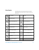
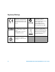
Safety Symbols The following symbols on the instrument and in the documentation indicate precautions which must be taken to maintain safe operation of the instrument.
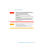
General Safety Information IV WA R N I N G • Do not use the device if it is damaged. Before you use the device, inspect the casing. Look for cracks or missing plastic. Do not operate the device around explosive gas, vapor, or dust. • Always use the device with the cables provided. • Observe all markings on the device before establishing any connection. • Turn off the device and application system power before connecting to the I/O terminals.
Environmental Conditions This instrument is designed for indoor use and in an area with low condensation. The table below shows the general environmental requirements for this instrument. CAUTION Environmental conditions Requirements Operating temperature 0 °C to 50 °C Operating humidity 20% to 85% RH non-condensing Storage temperature –20 °C to 70 °C Storage humidity 5% to 90% RH non-condensing The U2741A USB modular digital multimeter complies with the following safety and EMC requirements.
Regulatory Markings The CE mark is a registered trademark of the European Community. This CE mark shows that the product complies with all the relevant European Legal Directives. The C-tick mark is a registered trademark of the Spectrum Management Agency of Australia. This signifies compliance with the Australia EMC Framework regulations under the terms of the Radio Communication Act of 1992. ICES/NMB-001 indicates that this ISM device complies with the Canadian ICES-001.
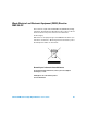
Waste Electrical and Electronic Equipment (WEEE) Directive 2002/96/EC This instrument complies with the WEEE Directive (2002/96/EC) marking requirement. This affixed product label indicates that you must not discard this electrical/electronic product in domestic household waste. Product Category: With reference to the equipment types in the WEEE directive Annex 1, this instrument is classified as a “Monitoring and Control Instrument” product. The affixed product label is as shown below.
VIII U2741A USB Modular 5.
Contents 1 Specifications 1 Product Specifications 2 Frequency specifications 5 Temperature specifications 2 6 Performance Test Calibration 7 Calibration Overview 8 Closed - case electronic calibration 8 Agilent technologies calibration services Calibration interval 9 Time required for calibration 9 Recommended Test Equipment Self-Calibration 8 10 11 Test Considerations 12 Input connections 13 Performance Verification Tests Overview 14 Performance Verification Tests 16 Zero offset verificat
Contents 3 Service 27 Types of Service Available 28 Extended service contracts 28 Obtaining repair service (Worldwide) Repackaging for Shipment Cleaning 30 31 Electrostatic Discharge (ESD) Precautions To Replace a Current Input Fuse Troubleshooting the modular DMM 4 Replacement Parts General Disassemble 32 33 34 35 To Order Replaceable Parts X 28 36 37 U2741A USB Modular 5.
Contents List of Tables Table 1-1 Table 1-2 Table 1-3 Table 1-4 Table 1-5 Table 1-6 Table 1-7 Table 1-8 DC accuracy ± 2 AC accuracy for voltage 3 Temperature coefficient for voltage 4 AC accuracy for current 4 Temperature coefficient for current 5 Frequency accuracy 5 Frequency sensitivity for AC voltage 5 Temperature accuracy ± (% of reading + no.
Contents XII U2741A USB Modular 5.
U2741A USB Modular 5.
1 Specifications Product Specifications DC specifications [1] Table 1-1 DC accuracy ± Function Range Input impedance Test current /Burden voltage, shunt resistance Accuracy (% of reading + % of range) Temperature coefficient 0 °C to 18 °C 28 °C to 55 °C Voltage [2] 100.000 mV 10 MΩ – 0.015 + 0.008 0.002 + 0.0008 1.00000 V 10 MΩ – 0.015 + 0.005 0.001 + 0.0005 10.0000 V 10 MΩ – 0.018 + 0.005 0.002 + 0.0005 100.000 V 10 MΩ – 0.018 + 0.005 0.002 + 0.0005 300.000 V 10 MΩ – 0.
Specifications [1] Specifications are based on 30 minutes warm-up time, NPLC 20 digit resolution, and calibration temperature 18 °C to 28 °C. For NPLC 0 and 0.025, add 0.01% of range. [2] 20% over range on all ranges except 300 VDC. Input protection up to 300 VDC. [3] Input protected with externally accessible 2 A, 250 V fast blown fuse. 1 [4] Specifications are for 4-wire ohm or 2-wire ohms using null function in AMM software. If without null function in AMM software, add 0.2 Ω additional error.
1 Specifications [3] Additional error to be added as frequency more than 30 kHz and signal input less than 10% of range. 30 kHz to 100 kHz: 0.003% of full scale per kHz. [4] Input signal has to be more than 50 Vrms. Table 1-3 Temperature coefficient for voltage Range Frequency (Hz) 20 ~ 45 45 ~ 10k 10k ~ 30k 30k ~ 100k 0.02 + 0.02 0.02 + 0.02 0.05 + 0.02 0.1 + 0.02 100.000 mVrms, Temperature coefficient 1.00000 V, 10.0000 V, 100.000 V, 250.
Specifications 1 Frequency specifications [1] Table 1-5 Temperature coefficient for current Range Temperature coefficient Frequency (Hz) 10.0000 mA, 100.000 mA, 1.00000 A, 2.0000 A 20 ~ 45 45 ~ 10k 10k ~ 30k 0.02 + 0.02 0.02 + 0.02 0.02 + 0.02 Table 1-6 Frequency accuracy Functions Range Accuracy (% of reading + % of range) Minimum input frequency Frequency 20 to 300 kHz 0.0200 +0.003 1 Hz Temperature coefficient (%) 0.
1 Specifications Temperature specifications Table 1-8 Temperature accuracy Function Thermistor type Range Accuracy Temperature coefficient Temperature 5 kΩ thermistor –80.0 °C to 150.0 °C Probe accuracy + 0.2 °C 0.002 °C –112 °F to 302 °F 6 U2741A USB Modular 5.
U2741A USB Modular 5.5 Digits Digital Multimeter Service Guide 2 Performance Test Calibration Calibration Overview 8 Recommended Test Equipment 10 Self-Calibration 11 Test Considerations 12 Performance Verification Tests Overview 14 Performance Verification Tests 16 This chapter contains performance test and calibration procedures. The performance tests procedures allow you to verify that the multimeter is operating within its published specifications.
2 Performance Test Calibration Calibration Overview WA R N I N G NOTE SHOCK HAZARD. Only service trained personnels who are aware of the hazards involved should perform the procedure in this chapter. To avoid electrical shock and personal injury, make sure to read and follow all test equipments safety instructions. Make sure you have read “Test Considerations” on page 12 before calibrating the instrument.
Performance Test Calibration 2 Calibration interval A one year interval is adequate for most applications. Accuracy specifications are warranted only if adjustment is made at regular calibration intervals. Accuracy specifications are not warranted beyond the one year calibration interval. Agilent does not recommend extending calibration intervals beyond two years for any application. Time required for calibration The U2741A can be automatically calibrated under computer control.
2 Performance Test Calibration Recommended Test Equipment The test equipment recommended for the performance verification and adjustment procedures is listed below. If the exact instrument is not available, substitute with a calibration standards of an equivalent accuracy. A suggested alternate method would be to use the Agilent 3458A 8½ - digits digital multimeter to measure less accurate yet stable sources.
Performance Test Calibration 2 Self-Calibration The self- calibration performs an internal self- alignment routine to optimize the signal path that affects measurement sensitivity, offset and trigger parameters. It is advisable for you to run self- calibration for the following situation: • Every 12 months or after 2000 hours of operation. • If the ambient temperature is higher than 10 °C from the calibration temperature. • To maximize the measurement accuracy. • When you experience abnormal operation.
2 Performance Test Calibration Test Considerations Errors may be induced by AC signals present on the input leads during the verification tests. Long test leads can also act as an antenna causing pick- up of AC signals. For optimum performance, all procedures should comply with the following recommendations: • Ensure that the calibration ambient temperature is stable and in between 18 °C and 28 °C. Ideally the calibration should be performed at 23 °C ±1 °C.
Performance Test Calibration 2 Input connections Test connections to the instrument are best accomplished using the dual banana plug with a copper wire short between two terminals for low- thermal offset measurement. Shielded, twisted- pair, Teflon interconnect cables of a minimum length are recommended between the calibrator and the multimeter. Cable shields should be earth ground referenced. This configuration is recommended for optimal noises and settling time performance during calibration.
2 Performance Test Calibration Performance Verification Tests Overview Use the Performance Verification Tests to verify the measurement performance of the instrument. The performance verification tests use the instrument's specifications listed in Chapter 1, “Specifications”. You can perform four different levels of performance verification tests: Quick verification A selected verification test.
Performance Test Calibration 2 If the instrument fails the quick performance check, adjustment or repair is required. Adjustment is recommended at every calibration interval. If adjustment is not made, you must establish a 'guard band', using no more than 80% of the specifications, as the verification limits. NOTE Make sure you have read “Test Considerations” on page 12 before doing the performance verification tests. U2741A USB Modular 5.
2 Performance Test Calibration Performance Verification Tests Zero offset verification This test is used to check the zero offset performance of the instrument. Verification checks are only performed for those functions and ranges with unique offset calibration constants. Measurements are checked for each function and range as described in the procedure on the next page. Zero offset verification test 1 Connect the Shorting Plug to the voltage HI and LO input terminals.
Performance Test Calibration 2 Table 2-2 Zero offset verification test Input Function [1] Short Quick check 100 mV Short Short Range 1V DC Volts Error from nominal 1 year ±8 µV Q ±50 µV 10 V ±0.5 mV Short 100 V ±5 mV Short 300 V ±15 mV Short 100 Ω ±8 mΩ [2] 1 kΩ ±50 mΩ [2] Short Short 2-Wire Ohms and 10 kΩ Q ±500 mΩ [2] 100 kΩ ±5 Ω Short 1 MΩ ±50 Ω Short 10 MΩ ±500 Ω Short 100 MΩ ±5 kΩ Short 4-Wire Ohms [1] Select NPLC 20 digit resolution.
2 Performance Test Calibration Gain verification This test checks the full- scale reading accuracy of the instrument. Verification checks are performed only for those functions and ranges with unique gain calibration constants. DC voltage gain verification test DC voltage configuration: (CONFigure[:VOLTage][:DC] [ [,resolution|MIN|MAX|DEF>]]) 1 Connect the calibrator to the front panel HI and LO input terminals.
Performance Test Calibration CAUTION 2 Set the calibrator output to 0 V before disconnecting it from the multimeter input terminals DC current gain verification test DC current configuration: (CONFigure:CURRent[:DC] [ [,resolution|MIN|MAX|DEF>]]) 1 Connect the calibrator to the front panel current HI and LO input connectors. 2 Select each function and range based on the input current in Table 2- 4. 3 Make a measurement and observe the result.
2 Performance Test Calibration Ohms gain verification test 2- wire ohms configuration: (CONFigure:RESistance [ [,resolution|MIN|MAX|DEF>]]) 4- wire ohms configuration: (CONFigure:FRESistance [ [,resolution|MIN|MAX|DEF>]]) 1 Select the Ohms function. 2 Select each range in the order based on the input resistance in Table 2- 5. Compare the measurement results with the appropriate test limits shown in the following table.
Performance Test Calibration 2 Frequency gain verification test Frequency configuration: (CONFigure:FREQuency [ [,resolution|MIN|MAX|DEF>]]) 1 Select the Frequency function. 2 Select each range in the order based on the input voltage and frequency indicated in Table 2- 6. Compare the measurement results with the appropriate test limits shown in the Table 2- 6. (Be certain to allow for appropriate source settling.
2 Performance Test Calibration AC voltage verification test AC voltage configuration: (CONFigure[:VOLTage]:AC [ [,resolution|MIN|MAX|DEF>]]) 1 Select the AC Voltage function. Select each range in the order based on the indicated input voltage and frequency. Compare the measurement results with the appropriate test limits shown in Table 2- 7. (Be certain to allow for appropriate source settling.
Performance Test Calibration CAUTION 2 Set the calibrator output to 0 V before disconnecting it from the multimeter input terminals. AC current verification test AC current configuration: (CONFigure:CURRent:AC [ [,resolution|MIN|MAX|DEF>]]) 1 Select the AC Current function. 2 Select each range in the order based on the input current and frequency. Compare the measurement results with the appropriate test limits shown in Table 2- 8.
2 Performance Test Calibration Optional AC voltage performance verification test These tests are not intended to be performed with every calibration. They are provided as an aid for verifying additional instrument specifications. AC voltage configuration: (CONFigure[:VOLTage]:AC [ [,resolution|MIN|MAX|DEF>]]) 1 Select the AC Voltage function. 2 Select each range in the order based on the input voltage and frequency.
Performance Test Calibration 2 Optional AC current performance verification test These tests are not intended to be performed with every calibration. They are provided as an aid for verifying additional instrument specifications. AC current configuration: (CONFigure:CURRent:AC [ [,resolution|MIN|MAX|DEF>]]) 1 Select the AC Current function. 2 Select each range in the order based on the indicated input current and frequency.
2 26 Performance Test Calibration U2741A USB Modular 5.
U2741A USB Modular 5.
3 Service Types of Service Available If your instrument fails during the warranty period, Agilent Technologies will repair or replace it under the terms of your warranty. After your warranty expires, Agilent offers repair services at competitive prices. Extended service contracts Many Agilent products are available with optional service contracts that extend the covered period after the standard warranty expires.
Service 3 Latin America: (305) 269 7500 Taiwan: 0800 047 866 Other Asia Pacific Countries: (65) 6375 8100 Or visit Agilent worlwide Web at: www.agilent.com/find/assist Or contact your Agilent Technologies Representative. Before shipping your instrument, ask the Agilent Technologies Service Center to provide shipping instructions, including what components to ship. Agilent recommends that you retain the original shipping carton for use in such shipments. U2741A USB Modular 5.
3 Service Repackaging for Shipment If the unit is to be shipped to Agilent for service or repair, be sure to: • Attach a tag to the unit identifying the owner and indicating the required service or repair. Include the model number and full serial number. • Place the unit in its original container with appropriate packaging material for shipping. • Secure the container with strong tape or metal bands.
Service 3 Cleaning Clean the outside of the instrument with a soft, lint- free, slightly dampened cloth. Do not use detergent. Disassembly is not required or recommended for cleaning. U2741A USB Modular 5.
3 Service Electrostatic Discharge (ESD) Precautions Almost all electrical components can be damaged by electrostatic discharge (ESD) during handling. Component damage can occur at electrostatic discharge voltages as low as 50 volts. The following guidelines will help prevent ESD damage when servicing the modular DMM or any electronic device. • Disassemble instruments only in a static- free work area. • Use a conductive work area to dissipate static charge.
Service 3 To Replace a Current Input Fuse The current input terminal is fuse protected. The fuse 2 A, 250 Vac, is located in the fuse folder on the front panel as shown in figure below. If you determine that the fuse is faulty, remove the fuse holder and replace this fuse, order Agilent part number 2110- 1422. Fuse Holder U2741A USB Modular 5.
3 Service Troubleshooting the modular DMM This section provides a brief check list of common failures. Before troubleshooting or repairing the modular DMM, make sure the failure is in the instrument rather than any external connections. Unit is inoperative • Verify that the AC/DC adapter is connected to the modular DMM. • Verify that the front panel power indicator is lit. • Verify that the USB cable is connected to the PC and the USB inlet in modular DMM.
U2741A USB Modular 5.5 Digits Digital Multimeter Service Guide 4 Replacement Parts To Order Replaceable Parts 36 General Disassemble 37 This section provides the information of the orderable replacement parts for U2741A USB modular digital multimeter. The parts available for replacement are listed in Table 4- 1 with the reference part numbers and the respective part names.
4 Replacement Parts To Order Replaceable Parts You can order the replacement parts from Agilent using the part number provided in the table below. To order replacement parts from Agilent, do the following: 1 Identify the Agilent part number of the required parts as shown in the replacement parts list. 2 Contact your nearest Agilent Sales Office or Service Center. 3 Provide the instrument's model number and serial number.
Replacement Parts 4 General Disassemble This chapter provides the step- by- step guide on how to dismantle the module and install the replacement assembly. To reassemble the module, follow the instructions in reverse order. NOTE The parts shown in the following figures are representative and may differ from what you have in your module.
4 Replacement Parts Step 2: Unscrew all the following indicated screws from the metal casing Screw Screw Step 3: Gently pull the front metal piece out, which is attached to the carrier and measurement boards. Step 4: Unscrew all the following indicated screws from the metal casing and remove the rear metal piece. Screw 38 Screw U2741A USB Modular 5.
www.agilent.