
Installation guide

12
How Does It Work? (continued)
N5183A MXG Signal Generator
• To perform user fl atness correction
(UFC) with external leveling to
improve power accuracy and fl atness.
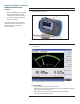
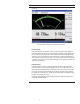
• To provide dual display measurement
of two USB power sensors.
User fl atness correction with external
leveling provides the ability to have
extremely fl at output power at the testing
interface beyond the signal generator RF
output connector. If an external device
(such as amplifi er, attenuator, coupler,
detector, divider or long cable) is placed
between the RF output connector and
the testing interface, it will introduce
additional gain or loss as well as
frequency response mismatch to the
whole system. Therefore it is necessary to
perform the UFC with external leveling to
remove this type of infl uence.
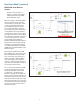
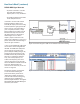
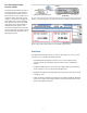
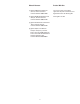
In this case, the U2000 Series USB power
sensor offers a solution integrated with
the MXG. The U2000 Series USB power
sensor is directly connected to front
panel’s USB port of MXG (see Figure 19)
provides remote programming function.
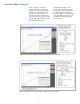
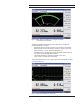
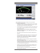
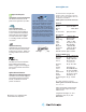
The MXG’s built-in UFC personality will
allow you to confi gure the calibration
array, start and stop frequency and
number of the frequency points to be
corrected. The setup function thus will
observe the difference between measured
power and calibrated power. The
correction factors of the UFC process are
shown as in Figure 20.
For details of operation and procedure
on UFC with external leveling and
power measurement, please refer to
“Agilent How to Utilize User Flatness
Correction with External Leveling Using
USB Power Sensor on MXG Signal
Generator, Application Note” and “Agilent
N5161A/62A/81A/82A/83A MXG Signal
Generators, User’s Guide”.
Figure 19 Connection diagram of USB sensor to MXG for UFC external leveling
Figure 20 Correction factors automatically performed and display on MXG