Agilent Compatibility of the U2000 Series USB Power Sensors with Agilent Instruments Application Note
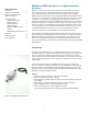
U2000 Series USB Power Sensor as an Agilent Instrument Accessory Table of Contents Introduction 2 U2000 Series USB Power Sensor’s Compatibility with Agilent Instruments 3 How Does It Work? • N5230C PNA-L Vector 4 Network Analyzer • E5071C ENA Vector 6 Network Analyzer • N9340x Handheld Spectrum 8 Analyzer • N5183A MXG Signal Generator 12 Conclusion 13 Related Literature 14 Product Web Site 14 Making an accurate power measurement requires both a power meter and a power sensor.
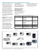
U2000 Series USB Power Sensor’s Compatibility with Agilent Instruments The Agilent instruments such as vector network analyzers, spectrum analyzers, signal generators, cable and antenna testers, and FieldFox RF analyzer are now compatible with the U2000 Series USB power sensors (see Table 1 and Figure 2). Each compatible instrument has built-in firmware to support the USB power sensor, unless it specifically requires N1918A Power Analysis Manager software or the Visual Basic Assistant (VBA) application.
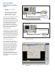
How Does It Work? N5230C PNA-L Vector Network Analyzer N5230C PNA-L • To perform the source-power calibration. GPIB • To provide output power in order to measure gain compression, intermodulation distortion, and other device parameters accurately. With source power calibration, the power at a certain point is calibrated, to be within the range of the uncertainty of the power meter and sensor.
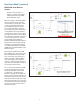
How Does It Work? (continued) Figure 6 and Figure 7 show the results of source power calibration for EPM and USB power sensors respectively. The PNA source is stepped through the specified range (in this example, stepped from 1 GHz to 6 GHz), and power (at 0 dBm) is measured with the power meter and USB power sensor. At each data point, the source power is adjusted until the measured power is within the specified accuracy level.
How Does It Work? (continued) E5071C ENA Vector Network Analyzer • To perform scalar analysis of a frequency converter which requires a VBA application through U2000 Series USB power sensor. E5071C ENA Series Network Analyzer with Frequency Offset Mode Option IF ± Df f1 ENA has a frequency offset mode (FOM) option used to measure the frequency converter device accurately. The “offset” of source and receiver port frequency can be defined precisely.
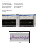
How Does It Work? (continued) Figure 11 and Figure 12 show the measurement result of “locked” and “drifted” LO signal by FOM mode (see the blue trace) and USB power sensor (see the red trace) respectively. The measurement result of the USB power sensor shows that it has good correlation with the FOM result at locked signal, and is stable with drifted LO signal.
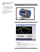
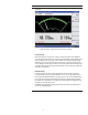
How Does It Work? (continued) N9340A Handheld Spectrum Analyzer • Turns the handheld spectrum analyzer into power meter. Displays power measurement with its user interface (UI), which integrates the display of power measurements. Instructions 1. Power up the N9340A. Connect the U2000 Series USB power sensor to the USB port of the N9340A (see Figure 13). Keystrokes surrounded by [ ] represent front-panel hardkeys of the instruments, while keystrokes surrounded by { } represent softkeys.
Instructions 3. Press {Zeroing ►} to perform the Internal or External Zeroing if necessary (see Figure 15). Figure 15 External and Internal Zeroing are performed to reduce the zero offset and noise impact in order to measure power accurately Internal Zeroing Internal zeroing uses an electronic switch to isolate the power sensor bulkhead from the internal measurement circuitry during the procedure, thereby allowing the sensor to be physically connected to an active RF source when internally zeroing.
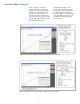
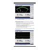
Instructions 4. Press {Return}. Press {Meas Disp ►} (see Figure 16). Figure 16 Meas Disp menu allows you to configure the display measurement and resolution The Meas Disp (Measurement Display) menu allows you to configure the measurement display as follows: • Disp Range: Indicates the top and bottom range of display measurement. • Resolution: Indicates the measurement resolution’s numeric type in four different levels (1, 2, 3 or 4). The default Resolution is 3.
Instructions 5. Press {Return}. Press {Meas Setup} (see Figure 18). Figure 18 Measurement Setup menu with meter-view display measurement Meas Setup (Measurement Setup) menu allows you to set up the relative measurement or set display offsets. • Freq: Allows setting for the frequency of the RF signal that you are measuring. It optimizes the accuracy and minimizes measurement uncertainty, especially when making comparative measurements between signals.
How Does It Work? (continued) N5183A MXG Signal Generator • To perform user flatness correction (UFC) with external leveling to improve power accuracy and flatness. • To provide dual display measurement of two USB power sensors. User flatness correction with external leveling provides the ability to have extremely flat output power at the testing interface beyond the signal generator RF output connector.
Dual Power Meter Display Function on MXG The dual power meter display function can be used to display the current frequency and average power of either one or two power sensors. For each channel, you can control the settings for On/Off, channel frequency, channel offset, averaging and measurement units, and the dual power meter display feature. To use two U2000 series power sensors with the MXG, an USB hub (with power supply) can be connected to the MXG’s front panel USB connector (see figure 21).
Related Literature Product Web Site [1] Agilent U2000 Series USB Power Sensors, Technical Overview Literature Number: 5989-6279EN For most up-to-date and complete application and product information, visit Agilent Web site at the following URL: [2] Agilent N9340A Handheld Spectrum Analyzer, Technical Overview Literature Number: 5989-5071EN www.agilent.
www.agilent.com For more information on Agilent Technologies’ products, applications or services, please contact your local Agilent office. The complete list is available at: Agilent Email Updates www.agilent.com/find/emailupdates Get the latest information on the products and applications you select. www.axiestandard.org AdvancedTCA® Extensions for Instrumentation and Test (AXIe) is an open standard that extends the AdvancedTCA for general purpose and semiconductor test.