
Technical data

Calibrator Output Operations 2
U1401A User’s and Service Guide 37
4 After selecting the required function, press or
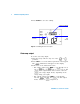
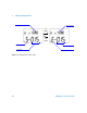
to select one of two modes: Continuous or Cycle. The
secondary display will indicate Cont or CyCLE, respectively
(Figure 2- 4 on page 38).
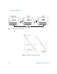
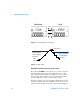
• Continuous mode (Cont): In this mode, the ramp signal is
repeated continuously. The signal will be generated
according to the amplitudes and number of steps
defined in the memory, with each step taking
approximately 0.33 seconds. For instance, according to
the default settings (Table 2- 2), the step size of the
positive slope is (end amplitude – start
amplitude)/number of steps. Therefore, the step size is
(1.5 V – (–1.5 V))/15 steps = 0.2 V for
±1.5000 V.
The step size of the negative slope is (start amplitude –
end amplitude)/number of steps. Therefore, the step
size is (–1.5 V – 1.5 V)/15 steps = –0.2 V for
±1.5000 V.
• Cycle mode (CyCLE): In this mode, only one cycle of the
ramp signal is generated. The signal will be generated
according to the amplitudes and number of steps
defined in the memory, with each step taking
approximately 0.33 seconds, and then the output
amplitude will be maintained at the final value of the
ramp signal.
5 Press OUTPUT to start the source output. The
annunciator will appear on the display.
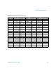
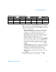
Table 2 - 2 Default settings for the autoramp output
Mode ±1.5000 V ±15.000 V ±25.000 mA
Position Amplitude Resolution Amplitude Resolution Amplitude Resolution
Start –1.5000 V 015 steps –15.000 V 015 steps –25.000 mA 025 steps
End +1.5000 V 015 steps +15.000 V 015 steps +25.000 mA 025 steps
3
4