
Technical data

Getting Started 1
U1401A User’s and Service Guide 17
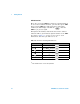
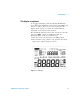
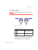
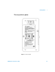
The terminals at a glance
Figure 1-7 Te r m i n a ls
This instrument has four terminals. The two terminals for
input functions are protected against overloads for the limits
specified in Table 1- 8. The other two terminals are for
output functions, with DC 30 V overload protection.
WARNING
To avoid damaging this instrument, do not exceed the rated input
limit.
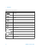
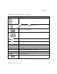
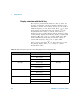
Table 1 - 7 Description of terminals
No. Description Function
1OUTPUT (Yellow) For constant voltage, constant
current, and square wave output
functions
2INPUT (Grey-white) For voltage, current, and
resistance measurements, and
diode and audible continuity tests
2
1