
Technical data

142 U1401A User’s and Service Guide
7 Performance Tests and Calibration
Output current calibration
1 Without exiting the calibration mode, turn the rotary
switch to any one of the “Current Input/Voltage Output”
positions.
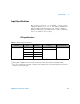
2 Connect the output terminals to a recommended
multimeter (refer to Table 7- 1 on page 131 for the
recommended test equipment).
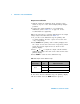
Follow the steps below to perform calibration for the output
voltage ranges and values listed in Table 7- 6:
1 As you enter each calibration step, the primary and
secondary displays show the output current value and
“- rdy- ” respectively.
2 Press OUTPUT. The primary and secondary displays show
the output current value and “00000” respectively, which
means the present output level is as shown on the
primary display.
3 Press or to adjust the output current until the
multimeter reading is the same as the value shown on the
primary display.
4 Press MODE to enter the next calibration step.
At the end of the last calibration step, the primary display
will show “PASS” after the MODE button is pressed.
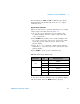
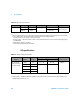
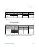
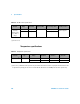
Table 7 - 6 Output current calibration steps
Current range
Calibration
step Output current value
25 mA
1 +00.000 mA
2 +11.000 mA
3 –11.000 mA
5
6