
Technical data

Performance Tests and Calibration 7
U1401A User’s and Service Guide 135
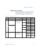
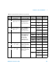
3 Turn the rotary switch to
. Press to select
frequency.
Connect the Normal
Hi-Low output terminals of
the calibrator to the
U1401A input terminals.
100 Hz 10 Hz
@ 16 mV
±5 mHz
100 kHz 20 kHz
@ 16V
±7 Hz
200 kHz 200 kHz
@ 24 mV
±30 kHz
4 Turn the rotary switch to
. Press
to select
duty cycle.
Connect the Normal
Hi-Low output terminals of
the calibrator to the
U1401A input terminals.
0.1% to 99% 50% @ 50 Hz
@ 5 Vac
0.3%
50% @ 800 Hz
@ 5 Vac
0.3%
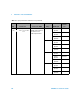
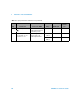
5 Turn the rotary switch to Ω. Connect the Normal
Hi-Low output terminals
and the AUX Hi-Low
output terminals of the
calibrator (with a
two-cable stacked
configuration) to the
U1401A input terminals.
500 Ω 500 Ω ±0.83 W
5 kΩ 5 kΩ ±8 W
50 kΩ 50 kΩ ±80 W
500 kΩ 500 kΩ ±800 W
5 MΩ 5 MΩ ±8 kW
50 MΩ 50 MΩ ±508 kW
6 Turn the rotary switch to
. Press
to
select DC.
Connect the AUX Hi-Low
output terminals of the
calibrator to the U1401A
input terminals.
0.05 A 0.045 A ±18.5 µA
0.5 A 0.45 A ±0.185 mA
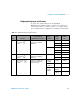
7 Turn the rotary switch to
. Press
to
select AC.
Connect the AUX Hi-Low
output terminals of the
calibrator to the U1401A
input terminals.
0.05 A 0.005 A
@ 1 kHz
±50 µA
0.045 A
@ 1 kHz
±0.29 mA
0.5 A 0.05 A
@ 50 Hz
±0.5 mA
0.45 A
@ 60 Hz
±2.9 mA
Table 7 - 3 Input performance verification tests (continued)
Step Tes t Fun c tio n Connection to 5520A Range 5520A output
Error from
nominal 1
year