
Technical data

Performance Tests and Calibration 7
U1401A User’s and Service Guide 133
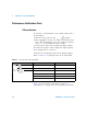
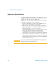
Input performance verification
To verify the input functions of the Handheld Multi- Function
Calibrator/Meter, perform the verifications tests listed in
Table 7- 3. Refer to Table 7- 1 on page 131 for the
recommended test equipment for verifying each function.
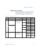
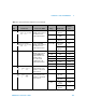
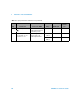
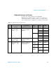
Table 7 - 3 Input performance verification tests
Step Tes t Fun c tio n Connection to 5520A Range 5520A output
Error from
nominal 1
year
1 Turn the rotary switch to mV.
Press
to select DC.
Connect the Normal
Hi-Low output terminals of
the calibrator to the
U1401A input terminals.
50 mV 0.05 V ±75 µV
–0.05 V ±75 µV
500 mV 0.5 V ±0.2 mV
–0.5 V ±0.2 mV
Turn the rotary switch to
. Press to select
DC.
5 V 5 V ±2 mV
–5 V ±2 mV
50 V 50 V ±20 mV
–50 V ±20 mV
250 V 250 V ±0.125 V
–250 V ±0.125 V
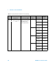
2 Turn the rotary switch to mV.
Press to select AC.
Connect the Normal
Hi-Low output terminals of
the calibrator to the
U1401A input terminals.
50 mV 50 mVrms
@ 45 Hz
±0.39 mVrms
50 mVrms
@ 5 kHz
±0.39 mVrms
50 mVrms
@20 kHz
±0.79 mVrms