
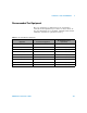
Technical data

132 U1401A User’s and Service Guide
7 Performance Tests and Calibration
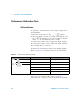
Performance Verification Tests
Self-verification
To perform a self- verification on the output voltage level of
the instrument:
1 Turn the rotary switch to the / position.
2 Short the input test leads for voltage measurement, then
press momentarily to zero the residual of thermal
effect until the measurement value is stable.
3 Connect the positive ends of input and output together.
4 Connect the negative ends of input and output together.
5 Set output value to +4.5000 V.
6 Observe the measurement value in the primary display.
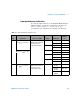
Refer to Table 7- 2 for functions that can be self- verified.
Table 7- 2 is for reference only. Refer to Chapter 8,
“Specifications,” on page 143 for the detailed specifications.
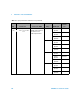
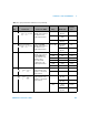
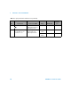
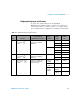
Table 7 - 2 Functions that can be self-verified
Rotary switch position Output value Measuring value (input)
/
+4.5000 V DC 4.5000 V
/
+25.0000 mA DC 25.0000 mA
/
100 Hz 100.00 Hz
0.39~99.60% 0.3~99.6%
±5 V AC 4.9586 V
±12 V AC 11.959 V