
Technical data


Maintenance 6
U1401A User’s and Service Guide 125
When servicing the instrument, use only the specified
replacement parts.
Table 6- 2 will assist you in identifying some of the basic
problems.
Table 6 - 2 Troubleshooting
Malfunction Identification of the problem
No LCD display after switching
ON
• Check the position of the slide switch. Set it to the M or M/S position
• Check the batteries. Recharge or replace the batteries if necessary
No beeper tone Check the setup mode to see if the beeper has been disabled (“OFF”). Select the
desired driving frequency
Failed to measure current Check fuse 1
No output signal when:
• the annunciator is
displayed.
• the OUTPUT key is pressed
and the annunciator
only appeared for a short
while before being replaced by
the annunciator.
• The batteries are low
• Check the position of the slide switch. Set it to the M/S position
• Check the external load to see whether the rated limit is exceeded.
• Check whether the loop has a 24 V power. If yes, use the special yellow test lead for
mA simulation (see Chapter 5, “Simulation Mode for mA Output”)
• Check fuse 2
No charging indication • Set the slide switch to the CHARGE position
• Check the external adapter to see whether the output is 24 VDC and whether it is
properly plugged in to the charging terminal
• Check the line power voltage (100 VAC to 250 VAC 47 Hz/63 Hz) and the power cord
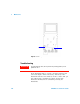
Remote control failure • Make sure that the optical side of cable is connected to the instrument and the text
side of the connector cover should be facing up
• Check the baud rate, parity, data bit, and stop bit (default settings: 9600, n, 8, 1)
• Install the driver for USB-RS232 on your PC