
Technical data

110 U1401A User’s and Service Guide
5 Application Examples
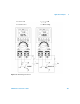
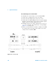
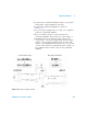
Voltage-to-current converter
In maintaining its differential input voltage at zero, the
operational amplifier shown in Figure 5- 14 forces a current
I = V
in
/R1 to flow through the R2 load in the feedback path.
This current is independent of the load.
1 Turn the rotary switch to the / position.
2 Manually select the DC 50 V range for the voltage
measurement.
3 Connect the red and black probe leads to the positive and
negative input terminals respectively.
4 Connect the red and black alligator leads to the positive
and negative output terminals respectively.
5 Connect the operational amplifier as shown in
Figure 5- 14.
6 Use a DC power supply with +15 V and –15 V outputs to
power the operational amplifier.
7 Gradually increase the U1401A output voltage from
+00.000 mV to +06.000 V while measuring the output
voltage of the operational amplifier. You will find the
output voltage increasing correspondingly from around
+00.000 V to around +12.000 V. You can then verify the
characteristic of the voltage- to- current converter by
performing the necessary calculations.
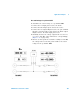
8 As an alternative, you can set the rotary switch to the
/ position and connect the input probe leads
in place of the meter A as shown in Figure 5- 14. You will
find that the measured current is proportional to the
voltage input into the operational amplifier.